LaserscanClippingPlugin
LaserscanClippingPlugin is a plugin used in UniversalPlantViewer Builder to manipulate laserscan data for the UniversalPlantViewer. It uses UPV session files (.upvc) exported from UniversalPlantViewer and merges clipping information with the initial session file.
Setup procedure
The LaserscanClippingPlugin is not an executable plugin and comes without a setup routine. After the file download, unpack the content of the container (zip) to the following directory:
%AppData%\CAXperts\Universal Plant Viewer Builder\Plugins\
If the folder Plugins does not exist, it needs to be created manually.
Clipping Definitions
Create Clipping Objects
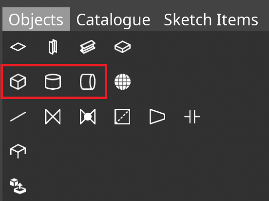
Before clipping, the clipping areas must be defined in UniversalPlantViewer with Sketching objects. In order to create a new Sketch, select the Sketching function from the main menu.
![]()
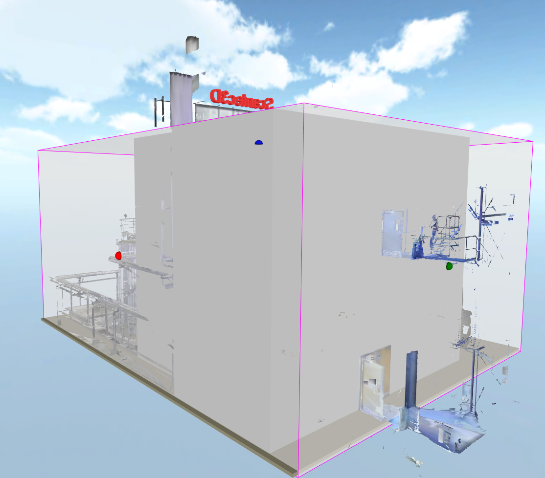
Place a Sketching object from the right-hand menu and place it within your laserscan object. Most commonly a box, horizontal or vertical vessel are used to define a clipping box or volume.
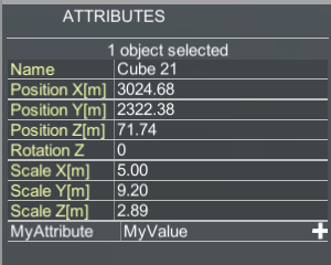
After the Sketch is placed, the position and size of the sketching object can be moved, resized or rotated about the z-axis to fit the needs of the clipping results. The sketching objects can be colourised, and the transparency can be adapted to make identification and orientation easier.
![]()
Clipping Attributes
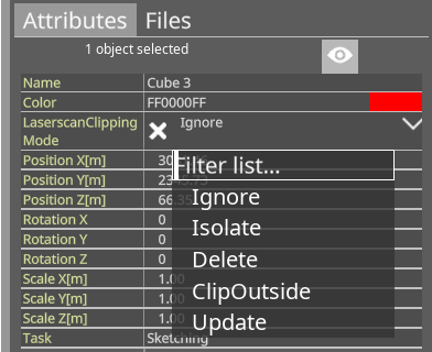
To define a sketching object as a clipping object, select the sketchobject and use the dropdown of the attribute LaserScanClippingMode. The default value Ignore means the object is not used for clipping.
LaserScanClippingMode – ClipOutside
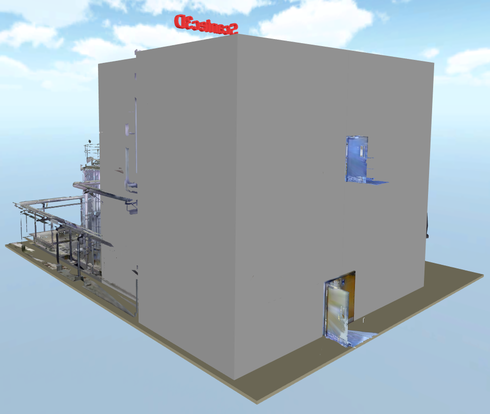
With the OuterBound value set, everything outside this boundary item will be cut away from the laserscan. Any other 3D data or sketches are not affected. For instance, there are several superficial parts outside the main target of the laserscan that are considered irrelevant and need to be removed.
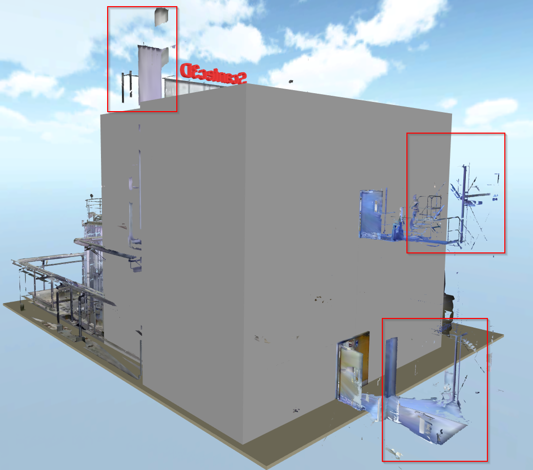
Place a Sketch item “box”, move and scale it to cover the area you want to keep. In this example, the bounding box is coloured white and set to semi-transparent in order to be able to see through the bounding box.
After saving the sketch as .upvc and building it with the UniversalPlantViewer Builder, only the laserscan-elements within the clipping box will remain.
LaserScanClippingMode – Isolate
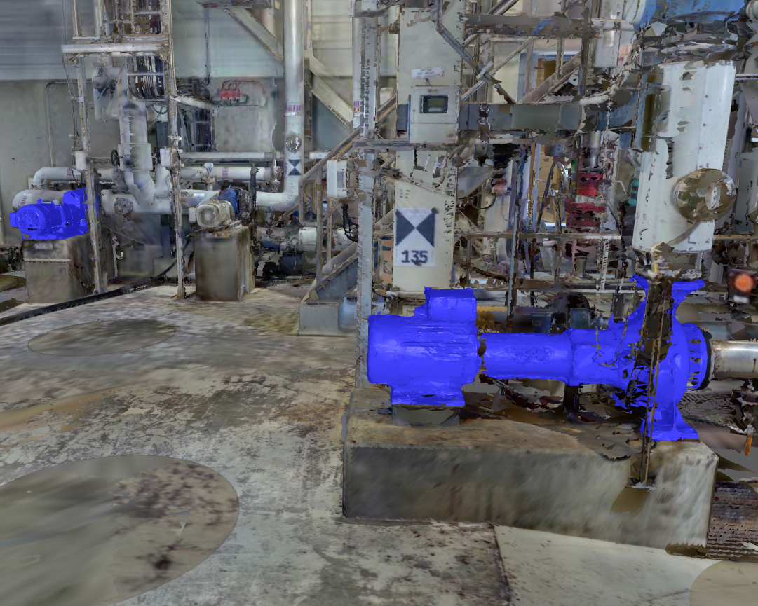
With the Isolate value set, you can use many different items to mark down a shape to be converted into an independent object as close as possible. For instance, if you want to pull out a pump from the laserscan and make it an object by itself.
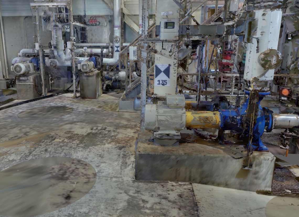
Place the Sketch items, move and scale them to cover the volume belonging to the desired item. The colour you choose for the sketching items will be the colour attached to the object after clipping.
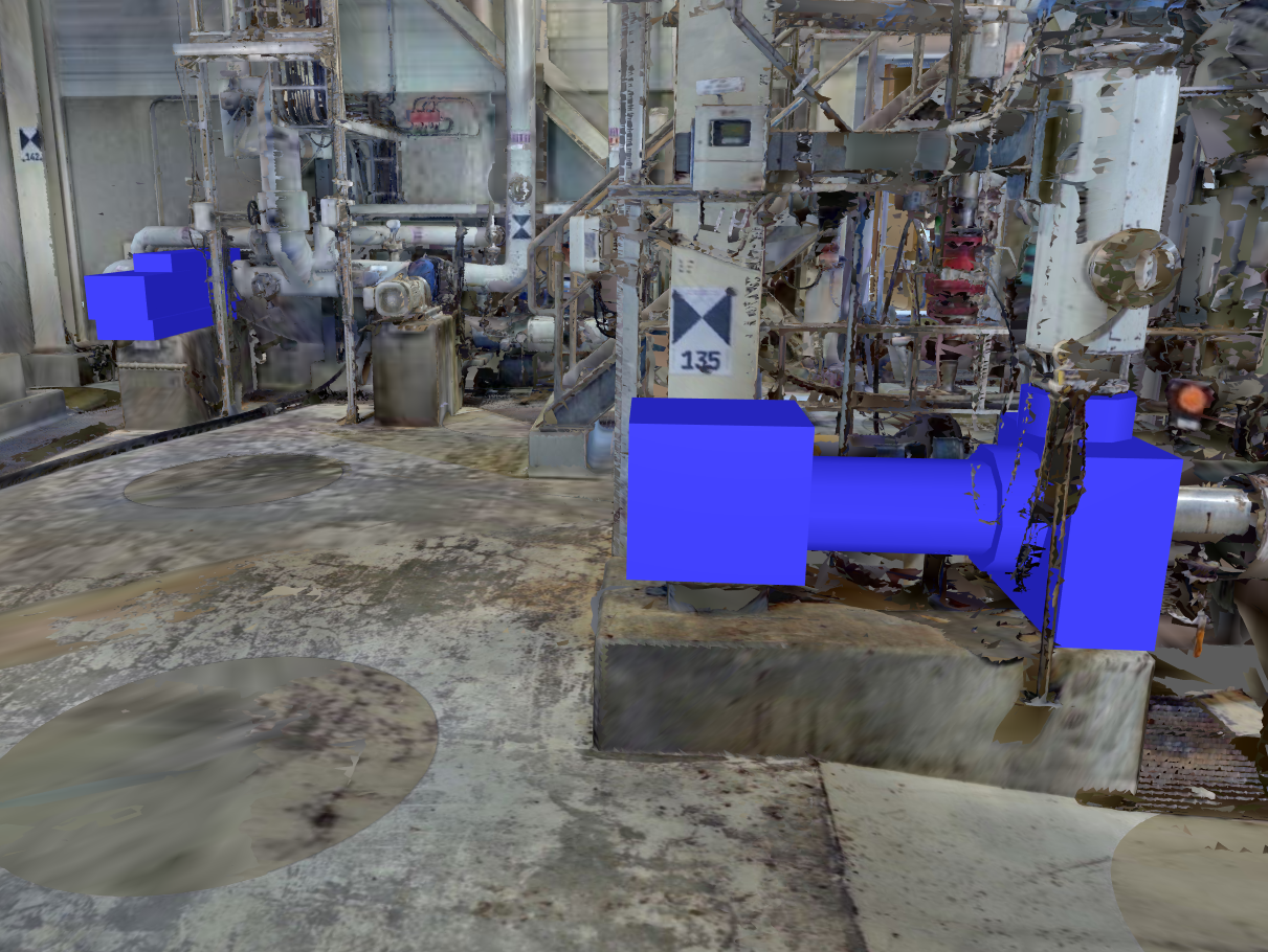
When saving the sketch as a .upvc, laserscan data located inside the shapes will be cut from the laserscan and replaced by a separate object when rebuilding the model with UniversalPlantViewer Builder. These objects can afterwards be recoloured ,hidden or found through the search function by their attributes individually.
The isolated objects can be provided with additional custom attributes. These attributes will stay part of the object even after clipping, making it possible to attach data, links etc. to the replaced object. See UniversalPlantViewer Documentation for more information about custom attributes.
LaserScanClippingMode – Delete
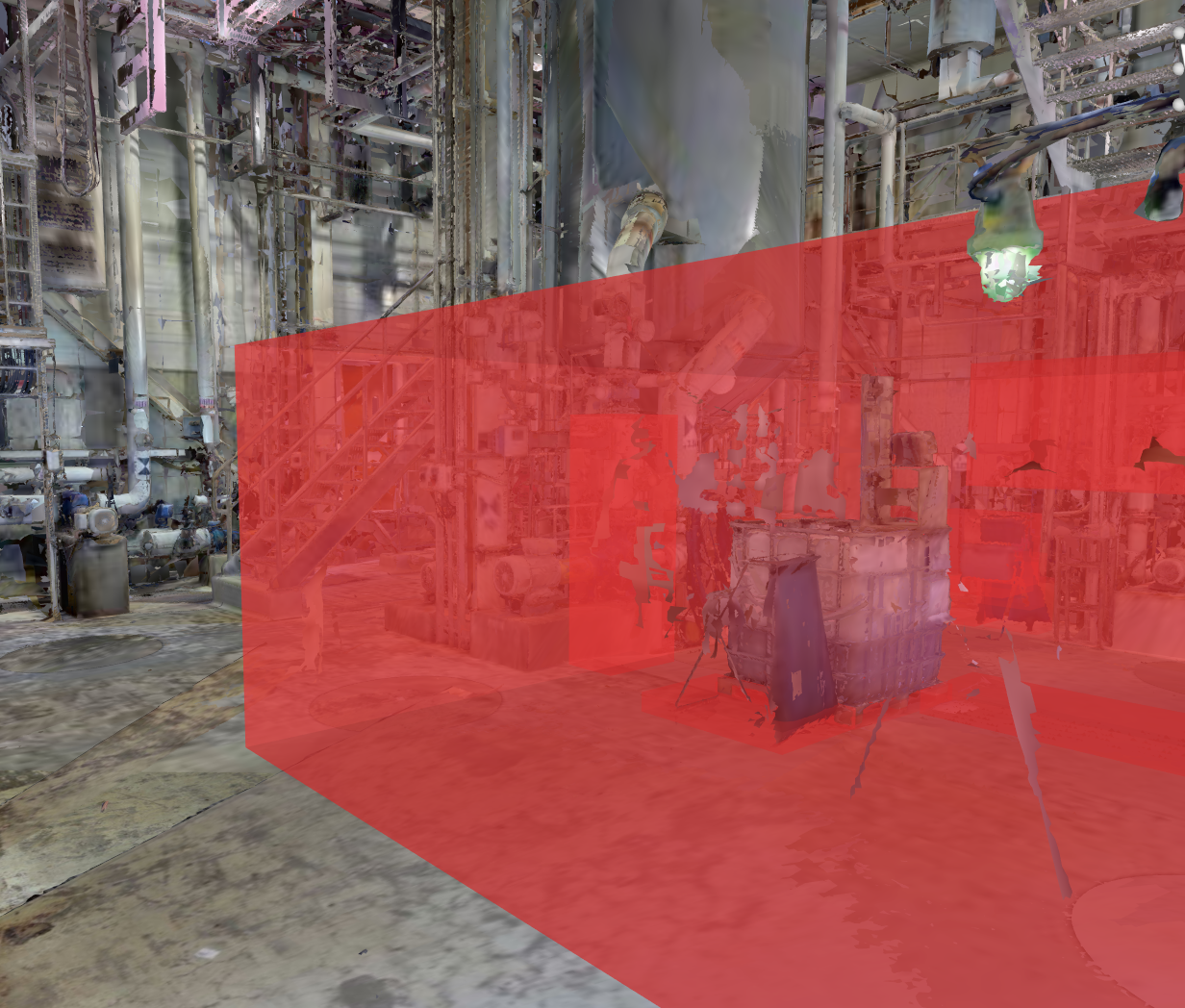
With the Delete value set, everything inside this boundary item will be cut out of the laserscan. Any other 3D data or sketches are not affected. For instance, there are parts of persons moving through the laserscan, leaving behind artefacts in the scan and need to be removed.
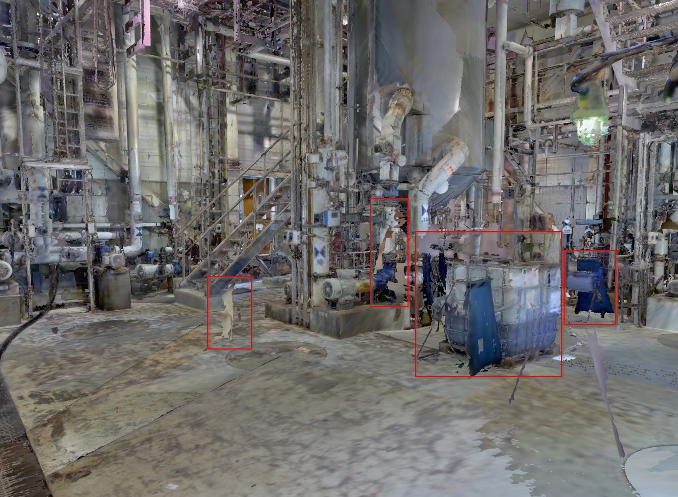
Place a Sketch item, move and scale it to cover the volume you want to cut out. In this example, the bounding box is coloured red and set to semi-transparent in order to be able to see through the bounding box.
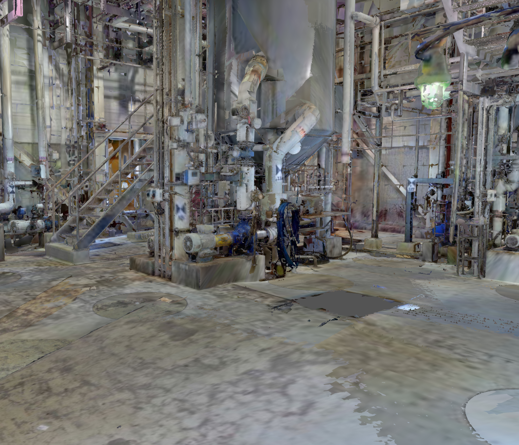
When saving the sketch as a .upvc, laserscan data located inside the shapes will be cut from the laserscan when rebuilding the model with UniversalPlantViewer Builder.
LaserScanClippingMode – Update
Using the value Update, specific parts of a laserscan can be comitted to an existing laserscan, leaving the rest of the older scan untouched. To do this, the UPVBPluginLaserscanClipping.xml file has to be edited. The file can be found at AppDataPlant Viewer Builder.xml
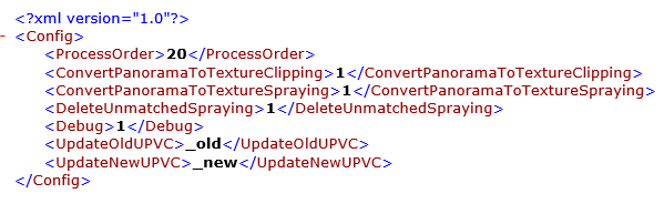
The Tag UpdateOldUPVC needs to contain the name of the .upvc of the model that is to be updated. UpdateNewUPVC needs to contain the name of the newer .upvc with the update-marked clipped objects. When building these two files in UniversalPlantViewer Builder, the odler model wil contain the clipped parts as they were in the newer versiion, while leaving the rest of the model.
Save Sketch Definitions
It is highly recommended to save the sketch definitions as UPV Sketch files (.upvf). This is not necessary for the clipping, but enables you to recall the sketch definitions, load them into later models or edit them subsequently.
Export Clipping Definitions
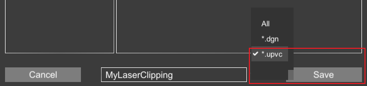
In order to use the now created clipping sketches for the actual clipping, it is necessary to save the files as UPV core files (.upvc) for handling with the UniversalPlantViewer Builder. Make sure to pick .upvc as save format and that the files are saved in the same folder as the initial source files used to build the model.
UniversalPlantViewer Builder settings
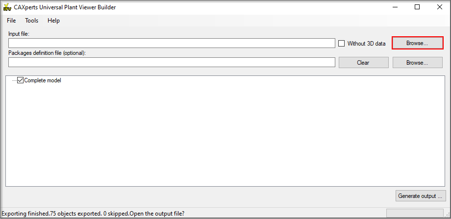
To create the final clipped laserscan model it is necessary to run the UniversalPlantViewer Builder to execute the clipping tasks defined by the clipping sketch items. To do so, start the UPV Builder and click on the [Browse…] button.
Selecting Sessions
In the following file open dialog, select the initial laFserscan session and all clipping sessions you wish to integrate into the new model (.upvc files) with the CTRL key on your keyboard pressed and confirm by clicking on the [Open] button.
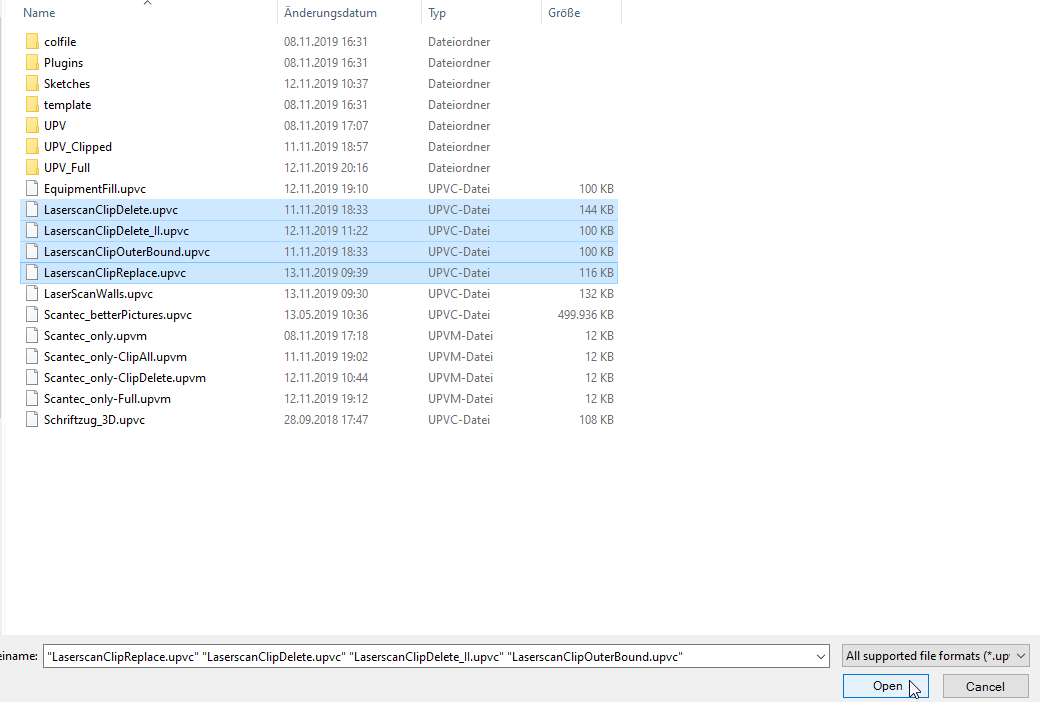
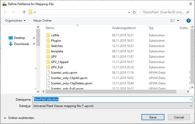
A new dialog appears, asking for a file name to save the collection of multiple session files (.upvm). Type in a filename you will recognise the file by later.
Activating the LaserscanClippingPlugin
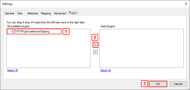
For the clipping, the LaserscanClippingPlugin must be activated first. Go to Tools → Settings in the menu bar and select the “Plugins” tab. Select the “UPVPluginLaserscanClipping” plugin from available plugins, transfer it to the used plugins by clicking on the [>] button and confirm your selection with [OK].
Selecting additional Attributes
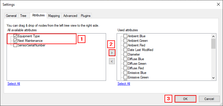
For integration of additional attributes, they first need to be activated, otherwise they will be ignored while creating the final clipped model. Go to Tools → Settings in the menu bar and select the “Attributes” tab, select the attributes you wish to use from the available attributes, transfer them to the used attributes by clicking on the [>] button and confirm your selection with [OK].
Output
Run the UniversalPlantViewer Builder as usual. The resulting UPV contains the final clipped model.