ReportAdapter for Smart® 3D
ReportAdapter for Smart® 3D is designed to export a Smart 3D attributes and graphics into a SQLite database, containing one table per task. The resulting records are compressed and internally resolved by code lists. The extraction of all data can be done without any knowledge of SP3D specific Report Creation. The philosophy is to use the Smart 3D Workspace Filters for creation of discipline specific reports.
Prerequisites
Supported operating systems:
Microsoft Windows Server 2008, 2012
Microsoft Windows 7 or later
Intergraph Smart 3D 2009 SP5 or later
ReportAdapter for Smart® 3D requires Smart 3D and a Smart 3D (S3D) licence seat on a Smart Licence Server.
Setting up ReportAdapter for Smart® 3D
Select plant
Start ReportAdapter for Smart® 3D and select your
Model Plant from the Plant Combo Box: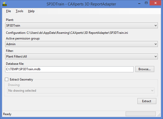
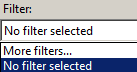
Select filter
To select a filter, click on the Filter Combo Box and select More filters….
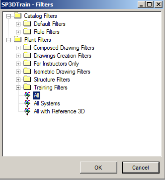
A window will open where all filters are listed, please select filter and click OK.
Select output
Browse with the Browse… button to select a location to create a Microsoft Access (.*mdb) or SQLite Database (*.db) in which the results will be shown.

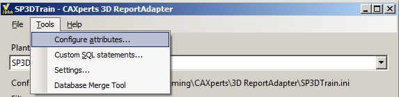
All the settings are stored automatically in the configuration file which is found under Tools → Settings.
Configure attributes
ReportAdapter for Smart® 3D contains a predefined set of attributes which are reported by default. Additionally customers can define and configure own attributes. No database specific or programming knowledge is required for customization of reportable Smart 3D attributes. A table is a combination of attribute sets, columns with identical names will be vertically aligned.
Add new table
To add a new table, right click in right panel and click New table
Attribute set
Each table consists of one or more attribute sets. Each attribute set holds the data for a specific top node. The result of one or more attribute sets is grouped together in the table they belong to in the output database.
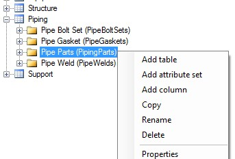
Add new attribute set
To add a new table, right click on a table and click New attribute set
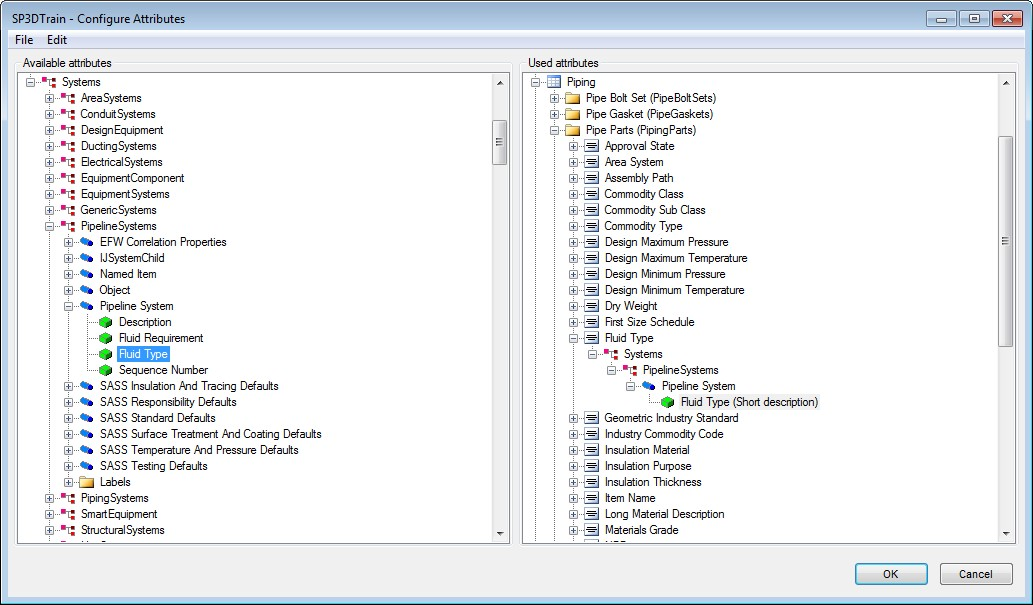
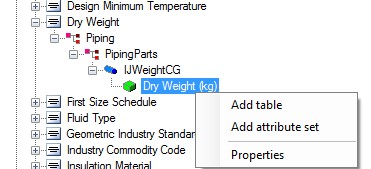
Add new attribute
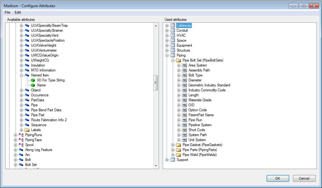
Drag and drop an attribute to the table on the right side. The attribute will then appear under the Attribute set.
Edit attribute set properties
To set the properties of a table, right click on the attribute set and select Properties.
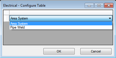
The type selected here defines the main item used for reporting, e.g. pipe component → run: pipe component selected → only runs that belong to the component are listed; run selected → also empty runs get listed.
Press OK to finish the configuration.
The changes will be applied on the next extraction. Smart 3D labels can be used similar to the direct object attributes. |
Extended attribute settings
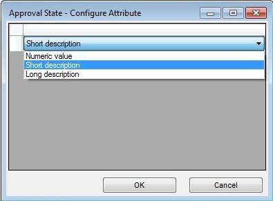
Click with the right mouse button on a code listed attribute to open extended attribute configuration form:
Code listed attributes can be extracted as:
Numeric values
Values decoded by short description
Values decoded by long description (default)
For Values with Units, the Units can be chosen:
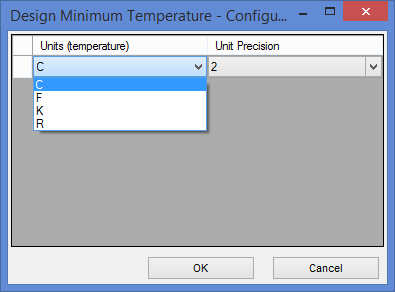
The changes will be applied on the next extraction. By default all attributes have common units configuration as defined in Menu->Unit settings. Here you can select custom unit for a specific attribute. |
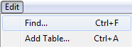
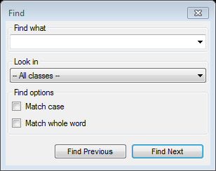
Find
Select Find… from the Edit menu to search for the available attributes:
Enter the search text in Find what and define the task name in Look in to search for the attribute in the given task:
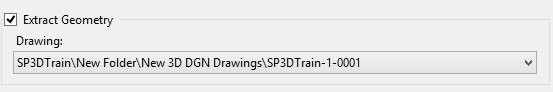
Geometry extraction
ReportAdapter for Smart® 3D allows extraction of geometry from Smart 3D, which is used by CAXperts UniversalPlantViewer and CAXperts S3D2PDS software.
Tick on Extract Geometry option and select existing 3D DGN drawing.
Prerequisites
Bentley MicroStation J (V7) has to be installed on the Workstation.
Empty 3D DGN drawing has to be created through the Smart 3D Drawing Console, e.g. like this:
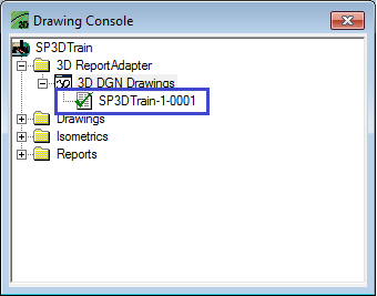
This 3D DGN Drawing is by ReportAdapter for Smart® 3D for the geometry extraction. The user needs the permission to update this drawing.Permission to create new filter in the folder (“Plant filters\3D ReportAdapter” by default).
Write permissions on Shared Content (Drawings\Catalog\Rules) to able create new View/Style rules.
Technical Hint regarding MicroStation limitation: The extraction of geometry using ReportAdapter for Smart® 3D is based on Intergraph Smart 3D export to 3D DGN file and has the same limitations: only graphical model data in a range of -26843 m to 26843 m in XYZ direction (for M/MM dgn-seed-file) and from -88069 ' to 88069 ' in XYZ direction (for '/" dgn-seed.file) are exported into MicroStation-files. Model data out of this range are not exported. |
Extraction
To start extraction of attributes and geometry if enabled click on Extract.
Additional SQL statements
Create additional SQL statements
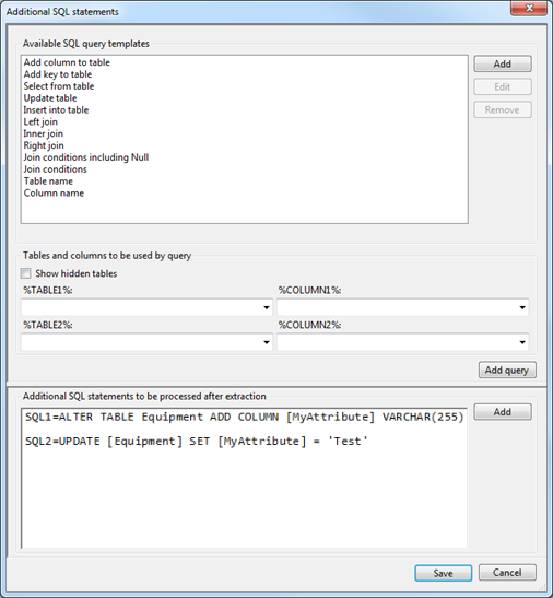
SQL statements to extend standard output tables with user defined attributes or to perform some other tasks (like creating additional tables, queries) can be defined using Tools → Additional SQL statements. They will be executed automatically after the extraction process has been completed.
The additional SQL statements can be typed in the Additional SQL statements to be processed after extraction field. They have to look like the following examples
SQL1=ALTER TABLE Equipment ADD COLUMN [MyAttribute] VARCHAR(255)
SQL2=UPDATE [Equipment] SET [MyAttribute] = 'Test'
Tables that can be used in the queries are those that will be created during extraction. Additional tables (if needed) have to be copied before extraction to the Template.mdb database which can be found in the application folder.
Use query builder
The included query builder can assist to create the SQL statements. Create a new statement with the Add button and add one of the Available SQL query templates to it. Add query or double-click on a list item will add the query at the cursor position or replace the selected text.
The Available SQL query templates look like:
UPDATE [%TABLE1%] SET [%TABLE1%].[%COLUMN1%]=
When the template is used, the %TABLE1% and %COLUMN1% fields will be filled with the table name and column name selected in the %TABLE1% and %COLUMN1% fields.
With the Show hidden tables field checked, all tables of the database can be selected to build the query. If it is not checked, only tables that will be displayed in UniversalReporter are available and tables created for internal use are hidden.
Create new SQL query template
User defined SQL query templates can be created. To add a new template, click the Add button and enter the template name.
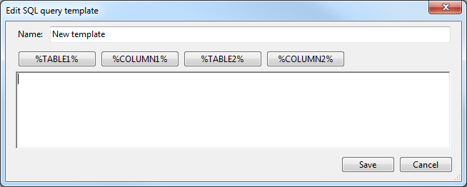
Fill in the text of SQL statement and the Placeholders for Tables and columns to be used by query textboxes by using the %TABLE"1% and %COLUMN1% buttons.
User defined templates can be deleted or modified using the Remove or Edit buttons.
The SQL text boxes support syntax highlighting. Depending on output database format: Microsoft Access (*.mdb) or SQLite (*.db) SQL syntax may be different. |
Settings
All program settings (selected tasks and filters, attributes, units of measure …) are stored automatically for each plant in the configuration file located by default in the user profile folder. The location of the configuration file can be changed by using menu Tools → Settings.
General
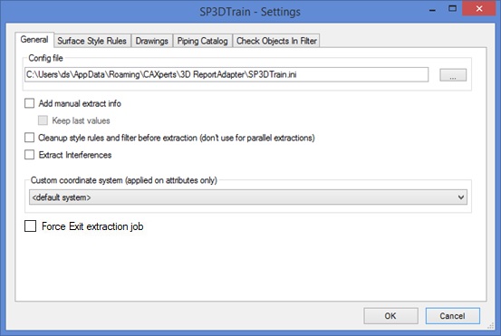
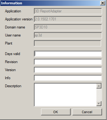
Add manual extract info: if enabled shows following dialog before extraction where the user can provide additional information evaluated by CAXperts UniversalReporter.
Clean-up style rules and filter before extraction (don’t use for parallel extractions): if geometry extraction is enabled this option removes all temporary style-rules and filters might left from last run of the software. In normal case You must not use this option when you run more the one extraction of ReportAdapter for Smart® 3D on your project at the same time.
Extract interferences: if geometry extraction is enabled this option extracts interference bubbles (graphic) with their attributes.
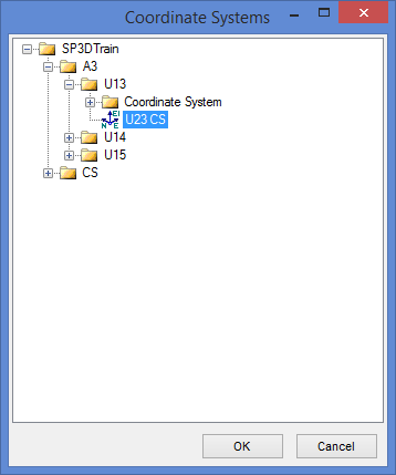
Custom coordinate system: to report coordinates using custom coordinate system (CS) instead of a global one (by default) click “more” and select CS to use.
Force Exit extraction job: additional possibility to ensure an extraction job to be finished by 3D ReportAdapter. This might be helpful especially for more extraction jobs scheduled in a row. This option is also available as a command line parameter. Force Exit extraction job - use 'lite' disconnect from S3D. Use this option only if you have problem with standard exit from 3D ReportAdapter.
Surface style rules
The colour is set in a standard S3D Surface Rule Style that is preconfigured from S3D Surface Rule Style settings. You can define here for the different aspects of the particular object type the MicroStation levels.
Select the rules to apply from the list of available Surface Rule Style on left hand side and press Add button.
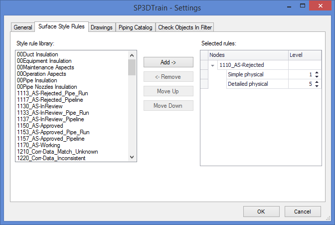
The rules are executed top->bottom. If no Style rules defined standard colours and MicroStation levels are used.
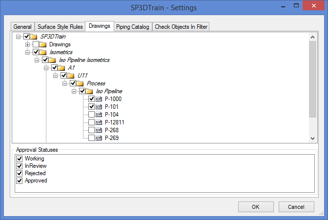
Drawings
Defines Isometric and Composed drawings to extract. To exclude drawings with a specific approval status, uncheck corresponding Approval Status in list.
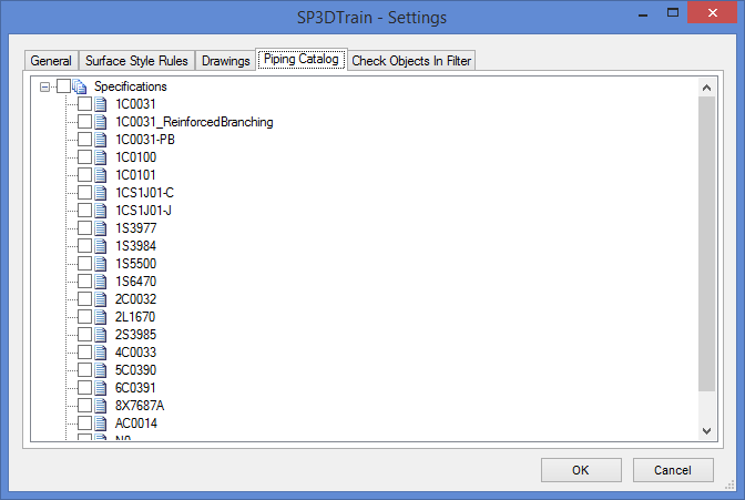
Piping Catalogue
Defines piping specifications to extract.
Check objects in filter
3D ReportAdapter can check if extracted object is included in selected filters.
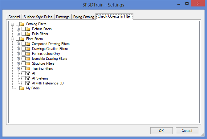
If at least one filter is selected, the software creates in resulting database ObjectsInFilter table with two columns Object OID and Filter Name. This functionality is useful to report for example volumes which includes the object.
Load settings from file
To import the settings into the plant configuration file use menu File → Load settings from file.
Save settings to file
To export the settings from the plant configuration file use menu File → Save settings to file.
Command line mode
The ReportAdapter for Smart® 3D can be used from the command line to automate the export of a Smart 3D data.
To then open the ReportAdapter batch mode help type in the installation path of ReportAdapter followed by “\3D ReportAdapter.exe” /?
"C:\Program Files\CAXperts\3D ReportAdapter\3D ReportAdapter.exe" /?Here’s the full syntax:
"3D ReportAdapter.exe" [?] [-plant:ExamplePlant] [-config:c:\config_file.ini] [-filter:My Filters\Filter1] [-output:output_file.mdb] [-cleanrules] [-drawing:Plant\New 3D DGN Drawings\Drawing-0001] [-extractgeometry] [-permissiongroup: Admin] [-forceattributes] [-forcegeometry] [-forceexit:1] [-log:D:\temp]| -plant plant_name | Smart 3D plant to process |
| -config config_file.ini | Config file which contains the settings for the extraction. If a configuration file is not defined, the last configuration will be used |
| -filter filter_name | Filter name from S3D Plant. Can be a Plant Filter or from My Filters. If a filter is not defined, the last configuration will be used |
| -output output_file.mdb | Output database. If Output database is not defined, the last configuration will be used |
| -cleanrules | Clean leftover temporary S3D3PDS-specific rules. This is an optional setting. |
| -drawing | Path to the 3D DGN-Drawing from S3D Drawing console |
| -extractgeometry | If this switch is set, S3D2PDS generates a PD_XPDA Backup file. |
| -permissiongroup | Permission-Group used for extraction |
| -forceattributes | If not defined only changed attributes will be extracted |
| -forcegeometry | If not defined only changed geometry will be extracted |
| -forceexit | Force Exit extraction job - use 'lite' disconnect from S3D. Use this option only if you have problem with standard exit from 3D ReportAdapter) |
| -log | If not defined, log file is placed in local Temp-directory |