ReportAdapter for SmartPlant® P&ID
The intended purpose of ReportAdapter for SmartPlant® P&ID is to perform an extraction of data used by Intergraph SmartPlant® P&ID (SPPID) into a local project database in Microsoft Access format.
Installation
Requirements:
Supported operating systems:
Microsoft Windows XP
Microsoft Windows Server 2003
Microsoft Windows Vista
Microsoft Windows 7 or later
Intergraph SmartPlant P&ID 4.3 or later
Graphical User Interface (GUI)
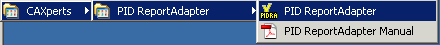
Invoking ReportAdapter for SmartPlant® P&ID
The utility can be invoked by clicking the ReportAdapter for SmartPlant® P&ID from the programs menu as shown below:
The following screen will appear:
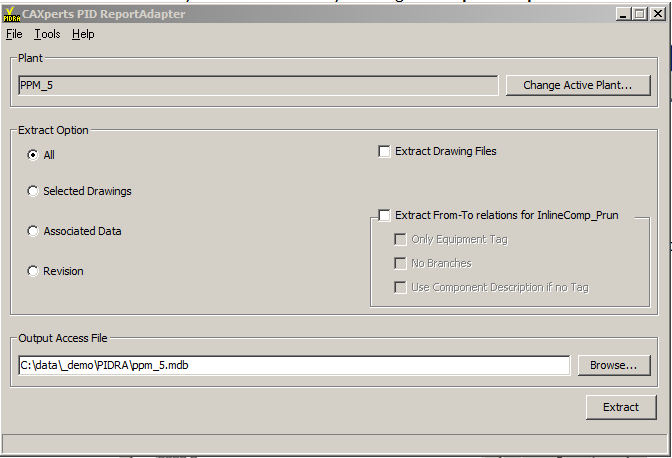
Loading a plant
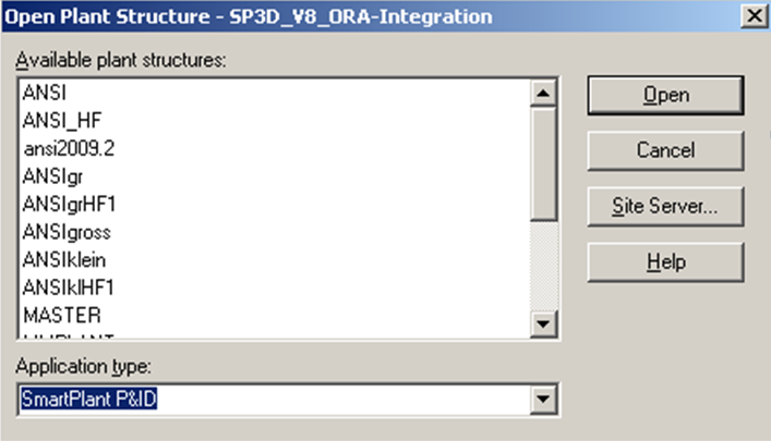
The software automatically connects to the active plant. It is displayed in the field Plant and can be changed using the Change active plant... button.
From the Open plant structure dialog, another plant of the active site can be selected. Plants of others sites can be accessed by using the Site server... button.
Before loading the plant data, the Output Access file needs to be specified using the Browse... button.
Extracting data
Using the Extract button starts the extraction from the selected plant. Different extraction options are available: All, Selected drawings, Associated data, Extract drawing files.
General extraction settings
All
The option All extracts all data of the plant without needing further configuration.
Selected drawings
The option Selected drawings starts the extraction with a dialog where the desired drawings can be selected.
A list with available drawings from the active project will appear. Check the designated drawings from the dialog and press OK to start the extraction.
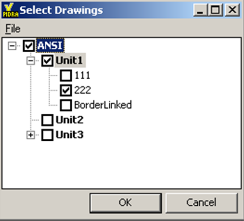
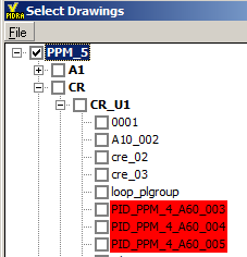
In Connected Workshare projects drawings which belong to the satellite are displayed in red so that the user is informed about the status of the drawings.
Associated data
The option Associated data starts the extraction with a dialog where the desired data can be defined using SQL statements.
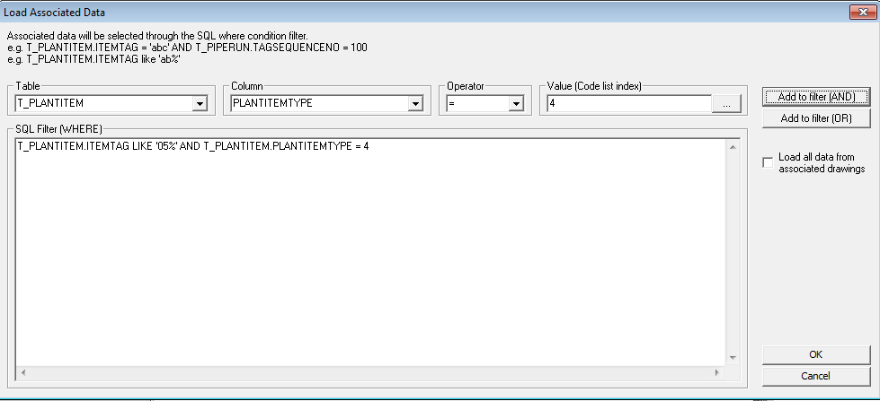
The above statement for instance will extract only pipe runs whose tags begin with “05”.
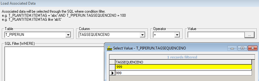
In a similar way it is possible to only extract pipe runs with FluidSystem “Water” or Nominal Diameter “100 mm”.
The same interface can also be used to search data for instance if a certain Sequence Number has been used in the plant (the yellow bar can be used to key in a search string) without performing the extraction:
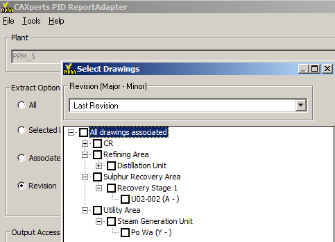
Revision
The option Revision allows the extraction of frozen data (only for revisions which do have an associated version). The dialogue will allow the selection of the “Last Revision” data or data for a specific revision:
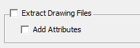
Extract drawing files
The option Extract drawing files copies the drawing files to a folder called “igr” located at the same level as the mdb file and renames the drawings to “.igr”.
The version of SmartSketch must be compatible to the version of SmartPlant P&ID otherwise the highlight function in UniversalReporter will not work.
Settings related to the from/to calculation
The following options can be used when extracting the from/to information:
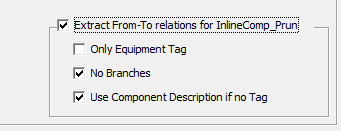
Only equipment tag: will report only equipment tags (no nozzle tags)
No branches: will not report branch connections
Use component description if no tag: will report the Piping Component Description attribute if the component tag is empty and if the component is an “EndComponent”
In addition to these settings the following changes were implemented:
TEMA heat exchangers
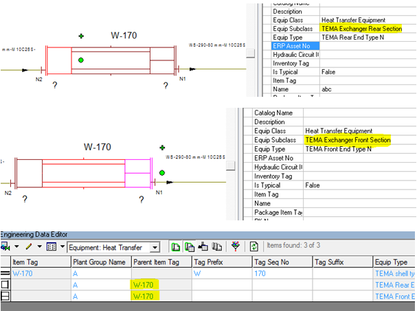 If the front and rear
sections do not have an own item tag defined then the shell item tag
will also be extracted as From/To information for pipe runs connected to
the front or the rear section.
If the front and rear
sections do not have an own item tag defined then the shell item tag
will also be extracted as From/To information for pipe runs connected to
the front or the rear section.
In the example above all runs connected to the parts of the heat exchanger will have “W-170” as from or to information.
Equipment with no tag
For equipment with no tag it is possible to use a variable which will tell the software which attribute to use as from/to information (“Name” or “Description” etc.).
This is done using the PID ReportAdapter ini file:
…\Program Files(x86)\CAXperts\PID ReportAdapter\PID ReportAdapter.ini
[FROM_TO]
Equipment_NoTag=Name
Keep original tables during extraction
For customers who want to keep the original tables which are created during the extraction there is a setting in the PID ReportAdapter ini file which can be used to prevent deletion of the original tables:
[Settings]
Pid_Delete_TempTables=0
If this parameter is added and set to the value 0 then the tables will not be deleted and in tables like t_equipment, t_piperun etc. will be available in the mdb file.
If the value is set to 1 then the tables will be deleted (this is the default behaviour if the parameter is not included in the ini file).
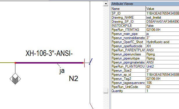
Attributes on drawing objects
A setting was implemented which is activating a check box for drawing extraction:
[Settings]
DrawingAttributes=1
If this parameter is added and set to the value 1 then the check box “Add attributes” is available in the PID ReportAdapter interface.
If the user selects it before the extraction then PID properties will be copied to the elements of the SmartSketch file (visible in the SmartSketch properties window).
Additional SQL statements
Create additional SQL statements
SQL statements to extend standard output tables with user defined attributes or to perform some other tasks (like creating additional tables, queries) can be defined using Tools → Additional SQL statements. They will be executed automatically after the extraction process has been completed.
The additional SQL statements can be typed in the Additional SQL statements to be processed after extraction field. They have to look like the following examples
SQL1=ALTER TABLE Equipment ADD COLUMN [MyAttribute] VARCHAR(255)
SQL2=UPDATE [Equipment] SET [MyAttribute] = 'Test'
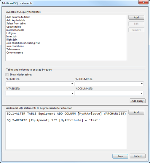
Tables that can be used in the queries are those that will be created during extraction. Additional tables (if needed) have to be copied before extraction to the template.mdb database which can be found in the application folder.
Use query builder
The included query builder can assist to create the SQL statements. Create a new statement with the Add button and add one of the Available SQL query templates to it. Add query or double-click on a list item will add the query at the cursor position or replace the selected text.
The Available SQL query templates look like:
UPDATE [%TABLE1%] SET [%TABLE1%].[%COLUMN1%]=
When the template is used, the %TABLE1% and %COLUMN1% fields will be filled with the table name and column name selected in the %TABLE1% and %COLUMN1% fields.
With the Show hidden tables field checked, all tables of the database can be selected to build the query. If it is not checked, only tables that will be displayed in UniversalReporter are available and tables created for internal use are hidden.
Create new SQL query template
User defined SQL query templates can be created. To add a new template, click the Add button and enter the template name.
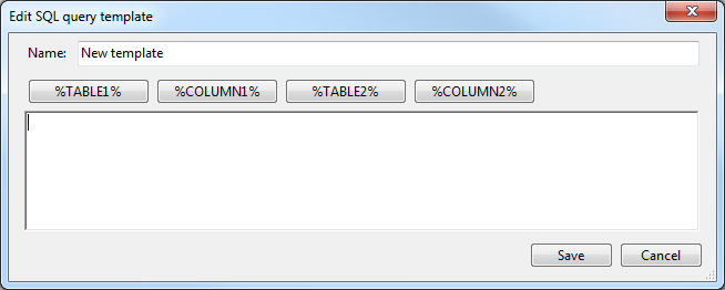
Fill in the text of SQL statement and the placeholders for Tables and columns to be used by query textboxes by using the %TABLE1% and %COLUMN1% buttons.
User defined templates can be deleted or modified using the Remove or Edit buttons.
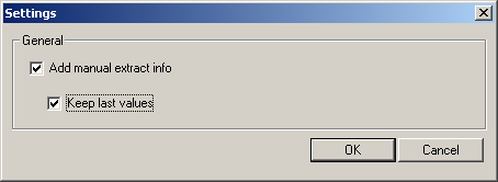
Add manual extract info
Under Tools - Settings the user can configure whether he wants to enter additional information that will be stored together with the extracted data. Only if Add manual extract info is checked, additional information can be added before extraction.
If Keep last values is checked, the Information window will be filled with the values last used for the selected plant.
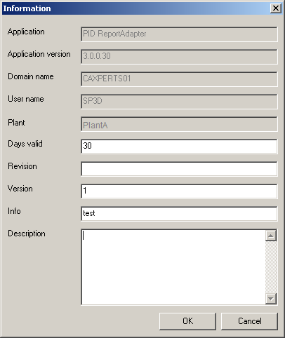
If the option Add manual extract info is set another window will come up before extraction, where information like revision number or a description can be added. This information is stored in the output database and can be recalled in UniversalReporter (or ApplicationReporter).
The field Days valid can be used to define a period during which the extracted data are valid. After this period UniversalReporter (or ApplicationReporter) will display a warning whenever the database is opened.
Configure attributes
General functions
Select Tools -> Attribute configuration... to open the Attribute configuration dialog.
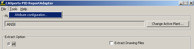
The following window appears.
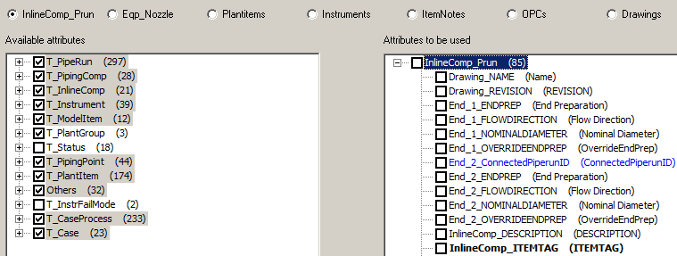
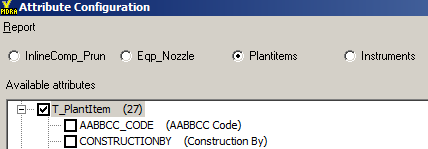
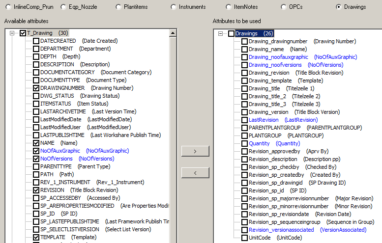
In this dialog it is possible to define attributes to be extracted.
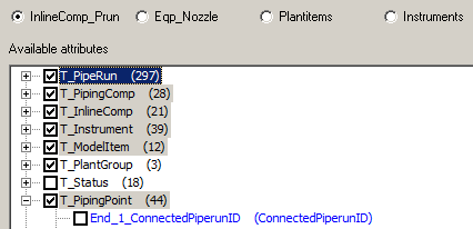
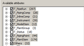
At present the attributes can be added for six objects, namely Inlinecomp_prun, Eqp_Nozzle, Plantitems, Instruments, ItemNotes, OPCs and Drawings.
Additional attributes (which are not available in SmartPlant P&ID and are created during the extraction) are displayed in blue (e.g. in the screenshot above “End_2_ConnectedPiperunID”)
The numbers displayed at the right side of the tables correspond to the number of available (left part of the window) and to the number of selected attributes (right side of the window).
Expand the tables and select the required attributes which can be transferred or removed from the Attributes to be used pane using > or < buttons.
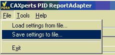
The attribute configuration will be saved in the folder %APPDATA%\CAXperts\PID ReportAdapter\ with the name PlantName.ini. The attribute configuration can also be saved for backup or for batch mode extraction using:
Attribute configuration specialties:
ParentPlantGroup and UnitCode
For SPEM Hierarchies like Plant\Area\Unit it is possible to extract the Parent PlantGroup information and also the UnitCode information:
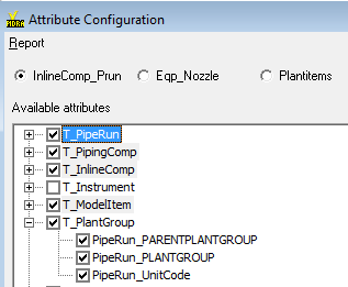
This allows easy filtering for instance on the Area. The selection is available on all objects with the exception of ItemNotes and OPCs.
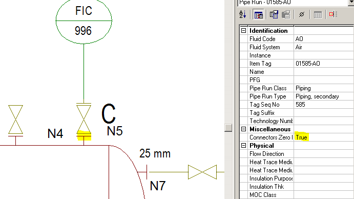
PipingPoint attributes including ConnectedPiperunID
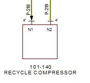
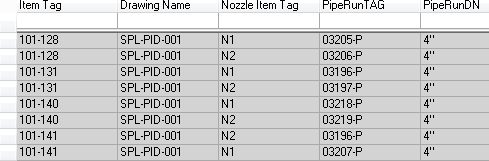
For the piping connect points 1 to 4 it is possible to extract attributes like nominal diameter, description etc. but also the SP_ID of the connected pipe run. This information can be used to create a report which displays the pipe run connected to the second side of a pressure reducing valve.
The result in UniversalReporter will look like this:

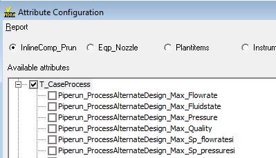
CaseProcess SI values (also other properties SI values)
The SI values can also be selected for extraction.
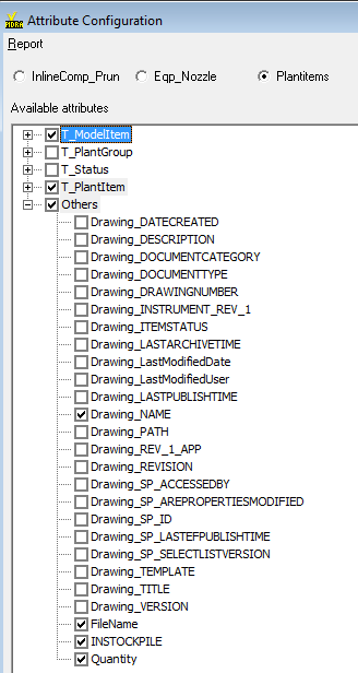
Filename and quantity
If “Filename” is selected (on the “PlantItem” object level) then the symbol name will also be extracted and it is possible to see how often a symbol is placed on a drawing.
If “Quantity” is selected (available on all object levels) then each extracted object will receive the quantity of “1” and in UniversalReporter it is possible to create “Sum_of_quantity” to identify the total amount of valves for instance.
Connectivity attributes for the relations “Equipment to PipeRun” and “Instruments to PipeRuns or Equipments”
Even though not visible in the attribute configuration interface the following two attributes are extracted:
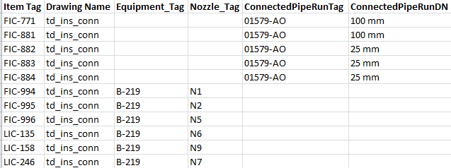
Nozzle_ConnectedPipeRunID for the Eqp_Nozzle table.
Instrument_ConnectedItemID for the Instruments table.
These attributes can be used to create reports where the piperuns connected to an equipment are listed (starting at the equipment object level) or where the instrument connections can be identified (connections can be to piperuns or equipment nozzles).
Example for the Equipment_PipeRun Relation:
Example for the Instrument Connection Report:
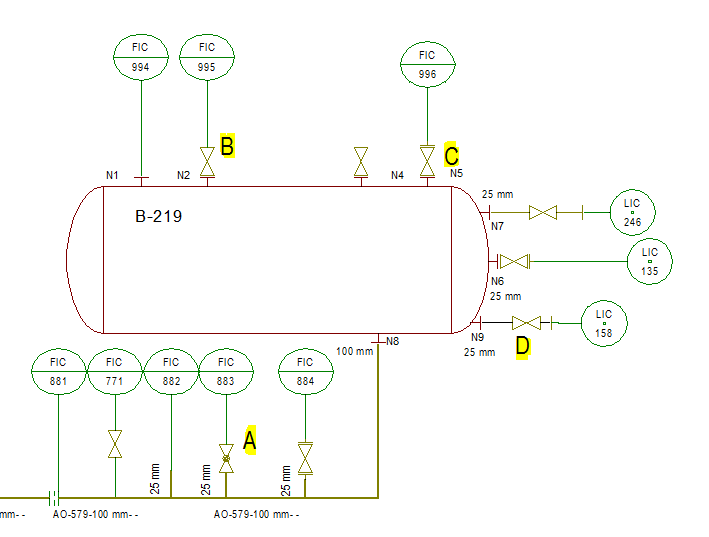
There are multiple ways to connect instruments to nozzles or piperuns.
The following connections (related to piping components placed between the connected piperun or the connected equipment nozzle and the instrument) have been modified in PID ReportAdapter:
A: Instrument is connected to a valve which is placed in a branch of the main piperun; the branch will return as connected object.
B: Instrument is connected to a valve which is connected to a nozzle (the piperuntype is Conn to process/Supply); here the nozzle will return as connected object.
C: Instrument is connected to t valve which is connected via “ZeroLength” piperun to a nozzle; here the nozzle will return as connected object.
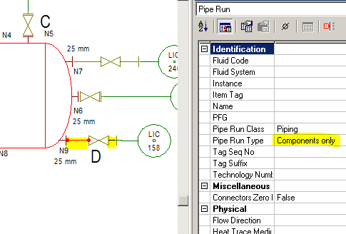
D: Instrument is connected to a valve which is placed in a piperun which is connected to a nozzle; the piperun has a special linetype; here the nozzle will return as connected object (in the example below the linetype is “Components only”).
The definition of the piperun type can be done in ..\PID ReportAdapter.ini with the following setting:
[Instr_Conn]
Nozzle_Pruntype = “Components only”
Details for C and D:
Result:
Disconnected piperuns having the same ItemTag
If “NotConnectedRuns” is selected (on the “InlineComp_Prun” object level below “Others”) then the number of disconnected piperuns having the same Tag will be calculated for the extracted dataset.

Within a drawing the function will check if the runs are graphically connected, across drawings the function will check if pipe runs are connected via OPCs. All results > 0 are pointing at duplicate pipe run tags which are not graphically connected.
Warning whenever the database is opened.
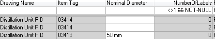
Identify number of LineNumberLabels placed on a piperun
For all pipe runs except instrument runs and zero-length pipe runs if the attribute “NumberofLabels” is selected and the label name(s) are defined in the plant specific ini file then the number of labels placed on each pipe run will be calculated during extraction.
In the ini file (.UserProfile\Appdata\Roaming\CAXperts\PID ReportAdapter\
<PlantName>.ini the relative path for the line label(s) to be checked must be added:
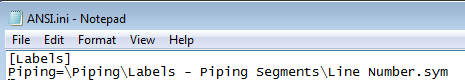
To define more than one label for checking a semicolon must be placed
between the labels as in the example below:
Piping=\Piping\Labels - Piping Segments\Line
Number.sym;\Piping\Labels - Piping Segments\Line Number_old.sym
All results different than 1 are the ones to be checked (0 means no label is placed, >1 means more than 1 label is placed on the same run.
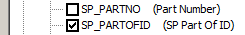
Identify the “Parent” relationship between components
Using the attribute “SP_PartOfId” (available in the PlantItem area for all components) it is now possible to extract relationships between actuator and valve, equipment component and equipment etc.
Number of versions and number of auxiliary graphic files for drawings
Using the attributes NoOfAuxGraphic and NoOfVersions (available in the drawing area) this information is calculated during extraction and is available as a field in UniversalReporter/QualityAssuranceModule.
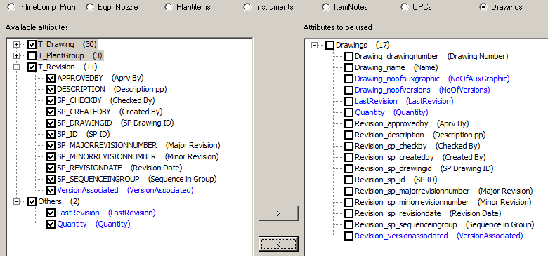
Drawing revision information
Attributes from t_revision can be selected for extraction. In addition it is possible to select the “LastRevision” which displays the latest revision of a drawing and also the “VersionAssociated” field which will display the information if there is a version associated to a revision.
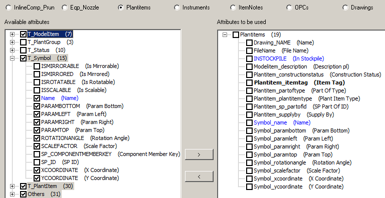
SymbolName and coordinates
The Symbol table was added to the extraction interface so that it is possible to select fields from the symbol table including the calculated field “Name” which refers to the name of the symbol (for ex. “Gate Valve”).
Parameter for all plant loops
In order to extract plant loops which do not have associated instruments the following parameter needs to be defined in the plant specific ini file (%Apdata%CAXperts\PIDReportAdapter folder):
[General]
AllLoops=1
MultiRep for equipment
A new attribute called “MultiRep” has been added to the
Equipment_Nozzle attribute configuration (in the “Others” area):
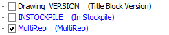
It gets calculated at extraction time and shows the value “True” for
MultiRepresentation equipment and “False” for other equipment.
As-Built information
A new plant attribute called “Asbuilt-name” has been added to the
_Info table so that it is available in
UniversalReporter as a parameter for the report
template creation.
It gets calculated at extraction time and shows the name of the As-Built
plant when data is extracted for projects.
Command line mode
PID ReportAdapter can also be used in command line mode, to extract all data from a plant to an mdb file automatically from a batch script. Use the following command to show the command line arguments:

Command line arguments:
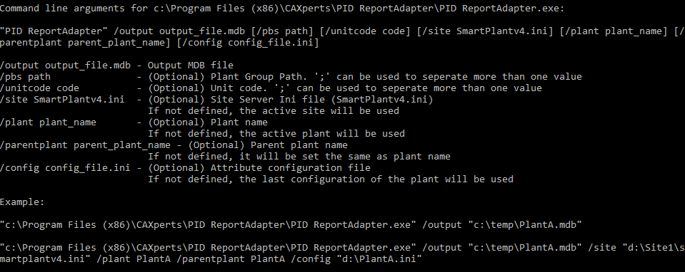
Example:
"C:\Program Files\CAXperts\PID ReportAdapter\PID ReportAdapter.exe" /output "c:\temp\PlantA.mdb"
"C:\Program Files\CAXperts\PID ReportAdapter\PID ReportAdapter.exe" /output "c:\temp\PlantA.mdb" /site "d:\Site1\smartplantv4.ini" /plant PlantA /parentplant PlantA /config "d:\PlantA.ini"
"C:\Program Files\CAXperts\PID ReportAdapter PID ReportAdapter.exe" /output d:\temp\1.mdb /pbs Refining Area\Recovery Unit;\Refining Area\Distillation Unit\a_* will save all drawings having names starting with “a_” and located in the “Refining Area\Recovery Unit” or “Refining Area\Distillation Unit”
"C:\Program Files\CAXperts\PID ReportAdapter PID ReportAdapter.exe" /output d:\temp\1.mdb /unitcode 03 will save all drawings located beneath the unit with unit code 03
The parameters /pbs and /unitcode must be used separately (either /pbs or /unitcode).
The attribute configuration ini file, used in the command line with the parameter /config, can be created using the menu File - Save settings to file.
The options of "Extract Drawing Files" and "Extract From-To relations for InlineComp_Prun" from the interactive mode are saved in the file
%APPDATA%\CAXperts\PID ReportAdapter\config.ini
(e.g. C:\Documents and Settings\UserName\Application Data\CAXperts\PID ReportAdapter\config.ini). For the command line mode, the two options will be read from the config.ini and will be used for the extraction.