S3D2PDS
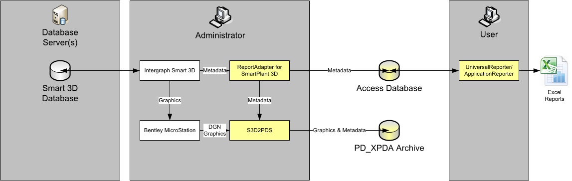
S3D2PDS is an add-on for CAXperts 3D ReportAdapter to create PD_XPDA backup files containing models and metadata.
Workflow
|
|
Intergraph Smart 3D needs Bentley MicroStation to export DGN files (without metadata). S3D2PDS triggers Smart 3D to export DGN files and adds metadata to the result. The quality of exported graphics will be exactly as good as in the DGN files created manually out of Smart 3D. |
| The metadata (attributes) can be configured using 3D ReportAdapter as described in the 3D ReportAdapter manual (attributes can be selected from all tasks available in 3D ReportAdapter). |
Prerequisites
To run S3D2PDS, a DGN export using certain settings has to be performed once in Smart 3D. To export a DGN file from Smart 3D the user has to
Install 7-zip (download it from http://www.7-zip.org )
Create a filter
Copy a delivered View Style to the SymbolShare
Copy some delivered Graphic Rules to the SymbolShare
Create drawing components
Create a drawing volume
For S3D2PDS, the user has to perform this just once per plant (all items on the list should be named “3D ReportAdapter”), afterwards S3D2PDS will modify the filter and trigger the drawing generation as needed.
First of all, install the graphic rules that come with S3D2PDS on your system (just copy the XML files to the relevant folder, they will ensure that tasks & aspects are mapped to the correct layers according to the table “layer destinations” in the annex of this document).
Create a filter
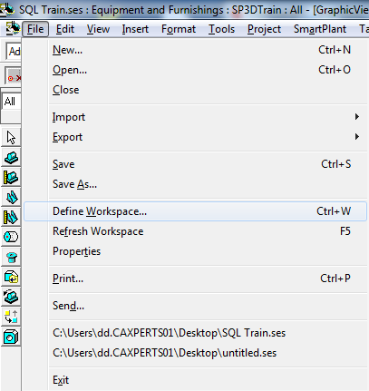
In Smart 3D, go to File → Define Workspace
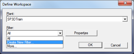
Select Filter: Create a New Filter
Change the Name to 3D ReportAdapter:
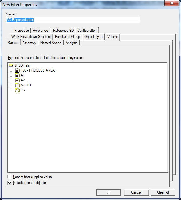
Select a single subsystem:
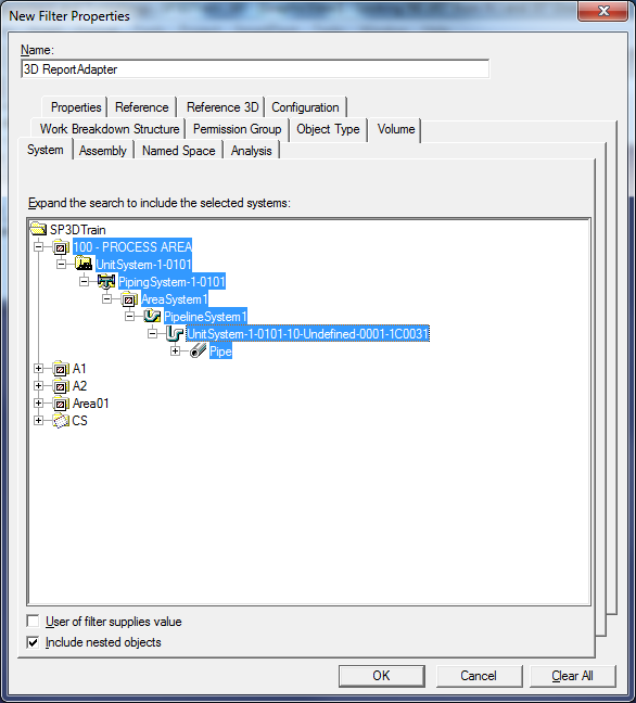
Press OK.
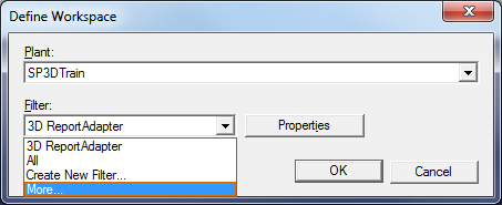
Now back in the Define Workspace window select Filter: More…
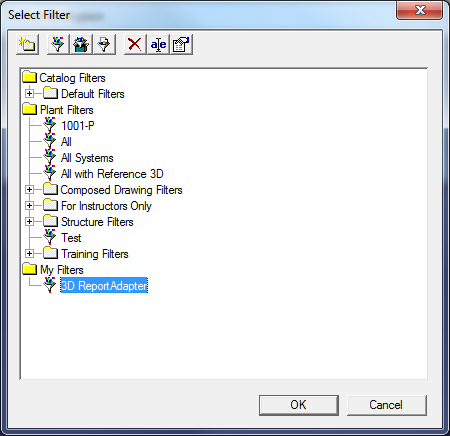
Drag and drop the filter 3D ReportAdapter from My Filters to Plant Filters to make a plant filter out of it:
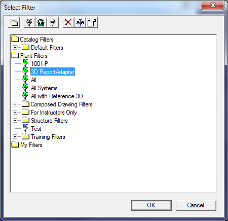
Press Cancel to close the Select Filter window.
Press Cancel to close the Define Workspace window.
Copy Graphic Rules and ViewStyle to SymbolShare
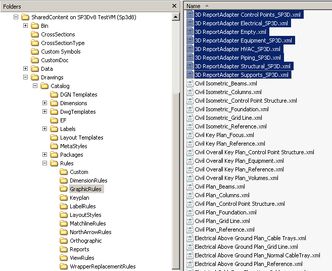
Copy the delivered Graphic Rules from 3D ReportAdapter Installation (C:\Program Files\CAXperts\3D ReportAdapter\Templates) into the appropriate place on SymbolShare:
Graphic Rules:
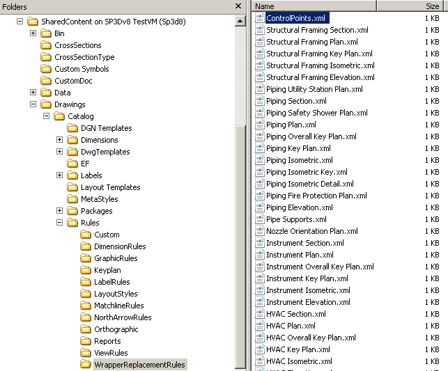
WrapperReplacementRules (ControlPoints.xml):
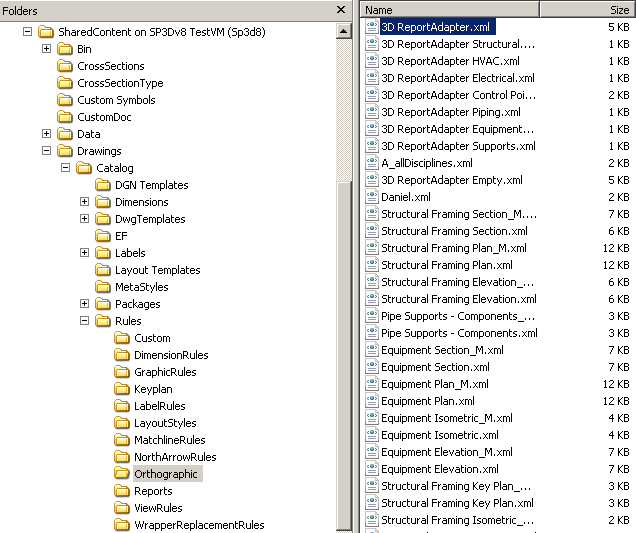
View Style (3D ReportAdapter.xml):
View Style and Graphic Rules must be available for a proper generation of the dgn-output!
Create drawing components
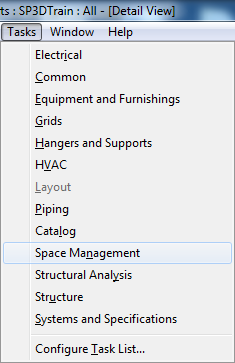
Now go to the Task → Space Management:
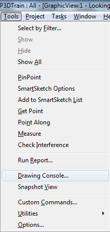
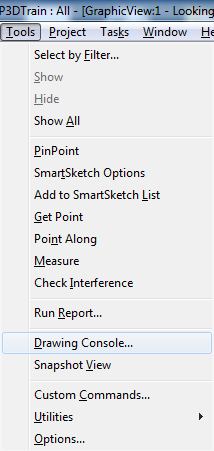
Open the drawing console using Tools → Drawing Console:
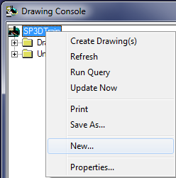
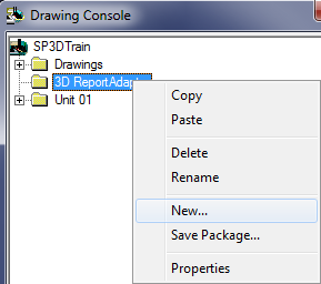
Right click the root node and select New from the context menu:
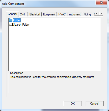
Select Folder and press OK:
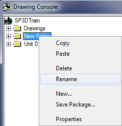
Now rename the new folder to 3D ReportAdapter:
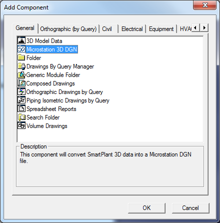
Right click on the 3D ReportAdapter node and select New from the context menu:
Select Microstation 3D DGN and press OK:
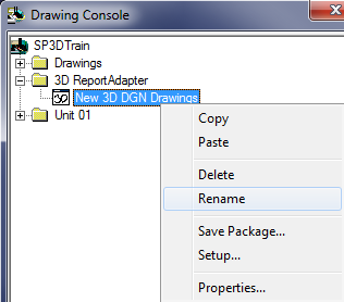
Rename New 3D DGN Drawings to 3D ReportAdapter:
Setup the 3D ReportAdapter node:
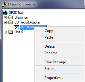
Select the Seed File mmdlsdz and the Style 3D ReportAdapter (Using More…/Properties):
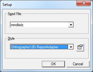
Press OK. Close the Drawing Console.
Create drawing volume
Activate the Engineering Point tool
( ).
).
Set Target to Origin
( ).
).
Place Drawing Volume by Two Points
( ).
).
Select Drawing Type More…:
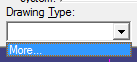
Select the 3D ReportAdapter drawing:
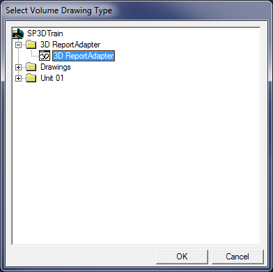
Press OK.
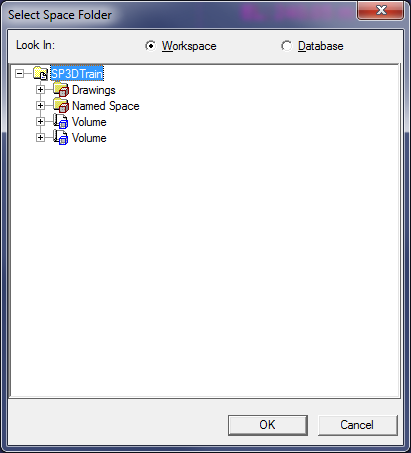
Select Space Folder More…:
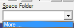
Select the root node and press OK:
Now enter -1000000, -1000000, -1000000 as the position of the lower coordinate:

(Don’t forget to lock the values using the lock symbol)
Click onto the view.
Now enter 1000000, 1000000, 1000000 as the position of the upper coordinate:

(Don’t forget to lock the values using the lock symbol)
Click onto the view.
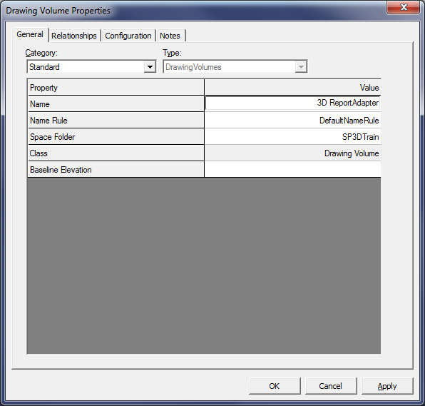
Now select the Space tab on the Workspace Explorer, right click the volume and select Properties from the context menu.
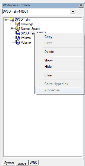
Change the name to 3D ReportAdapter and press OK:
Test run
Finally, test the drawing creation. Go to Tools → Drawing Console:
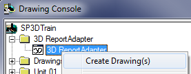
Right click the 3D ReportAdapter node and select Create Drawings:
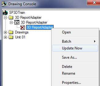
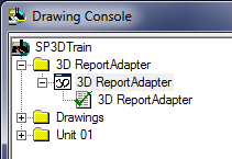
Right click the new 3D ReportAdapter node and select Update Now:
Now, Smart 3D will open MicroStation to create a drawing (this might take a couple of minutes). The result should look like this:
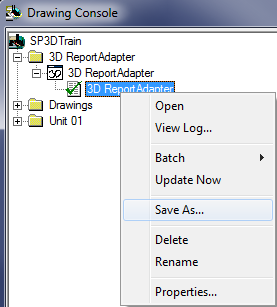
Finally, you can select Save As to save the drawing on your hard disk:
It is very important that this test run is passed successfully.
Please save the dgn-file (3D ReportAdapter.dgn) to disk and check the correct dgn-level assignment (see chapter 5). This is a prerequisite for the next steps.
Change of colours in the dgn-output
The colours in the dgn-output can be modified by changing the Graphic Rules for the respective objects which are processed onto a determined level in the dgn.
 E.g. if you want to change the colour for Piping-Objects on the
simple/detailed physical aspect, you have to open and modify the Graphic
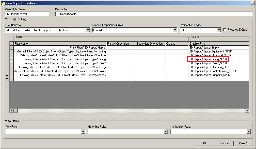
Rule in the View Style “3D ReportAdapter”:
E.g. if you want to change the colour for Piping-Objects on the
simple/detailed physical aspect, you have to open and modify the Graphic
Rule in the View Style “3D ReportAdapter”:
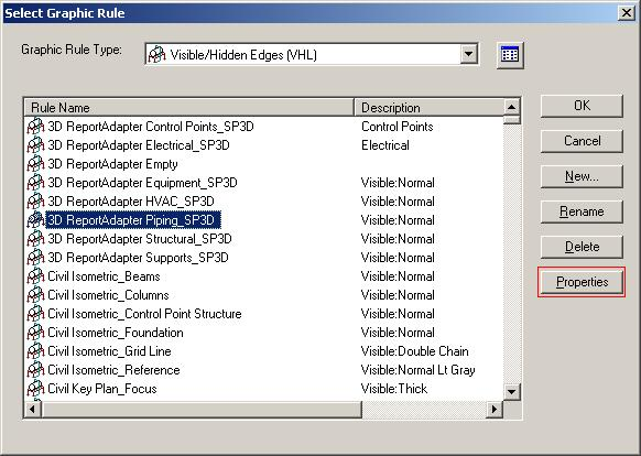
Open the properties of Graphic Rule “3D ReportAdapter Piping_SP3D”:
Here you can select the colour for the aspect of the respective Object-Type:
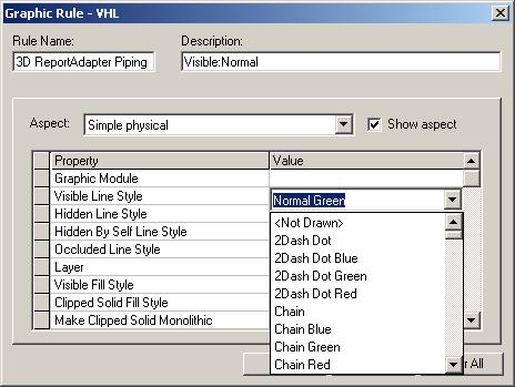
These are SmartSketch colours but during the export to dgn the next most similar MicroStation-Colour is automatically taken.
![]() Important: You must not change the Layer for Aspect of the
Object-Type!
Important: You must not change the Layer for Aspect of the
Object-Type!
Usage of the software
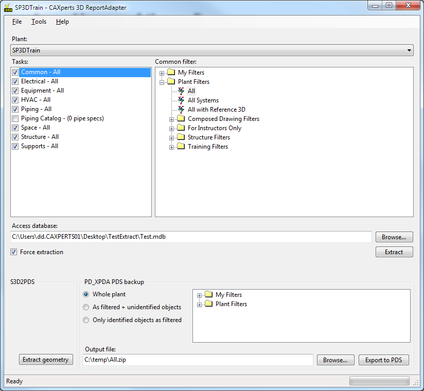
After the user installs the S3D2PDS licence key, a textbox PD_XPDA backup output file will be shown in 3D ReportAdapter. Select the name of the output file there.
Use the standard 3D ReportAdapter functions to create the attribute database. (for information on how to use 3D ReportAdapter or install the licence file see the 3D ReportAdapter Manual)
Press Extract Geometry to create a second database containing the per-part-DGN-files.
Press Export to PDS to create a PD_XPDA backup output files containing both graphics and metadata of the part of the selected model as specified in Tasks and Filters (i.e. the user can also partly extract data to the backup file).
Command line mode
The ReportAdapter for SmartPlant® 3D can be used from the command line to automate the exportation of a SmartPlant 3D data.
To then open the ReportAdapter batch mode help type in the installation path of ReportAdapter followed by “\3D ReportAdapter.exe” /?
C:\>“C:\Program Files\CAXperts\3D ReportAdapter\3D ReportAdapter.exe” /?
"3D ReportAdapter.exe" [/plant plant_name] [/config config_file.ini] [/output output_file.mdb] [/task Piping [/filter area1]] [/task Piping Catalog [/filter spec1] [/filter spec2]] [/force]
| {.Definition}/plant plant_name | SmartPlant 3D plant to process |
| {.Definition}/config config_file.ini | Config file which contains the settings for the extraction. If a configuration file is not defined, the last configuration will be used |
| {.Definition}/output output_file.mdb | Output database. If Output database is not defined, the last configuration will be used |
| {.Definition}/task task_name | Task name to extract, followed by the filter. If no tasks are defined, the last configuration will be used |
| {.Definition}/filter filter_name | Filter name, applied to the previously defined task. Multiple filters can be defined for Piping Catalog task |
| {.Definition}/force | Force extraction |
| {.Definition}/pdxpdafile output.zip | PD_XPDA output file. |
| {.Definition}/execute mode | Use PDS0, PDS1 or PDS2 for mode (the number after PDS specifies the geometry filter setting) |
Sample batch file to export the whole plant “SP3DTrain”:
@ECHO OFF
"C:\Program Files (x86)\CAXperts\3D ReportAdapter\3D ReportAdapter.exe" /plant SP3DTrain /force /pdxpdafile "c:\temp\s3d2pds.zip" /execute pds0
"C:\Program Files\7-Zip\7z.exe" e "c:\temp\s3d2pds.zip" -o%1
REM Missing: Rescale
PAUSE
Layer designations in DGN-Output
| Layer | Task | Aspect |
|---|---|---|
| 1 | Piping | Simple/Detailed Physical |
| 2 | Piping | MoldedForms (only for SM3D) |
| 3 | Piping | Insulation |
| 4 | Piping | Operation |
| 5 | Piping | Maintenance |
| 6 | Equipment | Physical |
| 7 | Equipment | MoldedForms (only for SM3D) |
| 8 | Equipment | Insulation |
| 9 | Equipment | Operation |
| 10 | Equipment | Maintenance |
| 11 | Structural | Simple/Detailed Physical |
| 12 | Structural | MoldedForms (only for SM3D) |
| 13 | Structural | Insulation |
| 14 | Structural | Operation |
| 15 | Structural | Maintenance |
| 16 | HVAC | Simple/Detailed Physical |
| 17 | HVAC | MoldedForms (only for SM3D) |
| 18 | HVAC | Insulation |
| 19 | HVAC | Operation |
| 20 | HVAC | Maintenance |
| 21 | Electrical | Simple/Detailed Physical |
| 22 | Electrical | MoldedForms (only for SM3D) |
| 23 | Electrical | Insulation |
| 24 | Electrical | Operation |
| 25 | Electrical | Maintenance |
| 26 | ControlPoints | Simple/Detailed Physical |
| 27 | ControlPoints | MoldedForms (only for SM3D) |
| 28 | ControlPoints | Insulation |
| 29 | ControlPoints | Operation |
| 30 | ControlPoints | Maintenance |
| 31 | Space | Simple/Detailed Physical |
| 32 | Space | MoldedForms (only for SM3D) |
| 33 | Space | Insulation |
| 34 | Space | Operation |
| 35 | Space | Maintenance |
| 36 | Grids | Simple/Detailed Physical |
| 37 | Grids | MoldedForms (only for SM3D) |
| 38 | Grids | Insulation |
| 39 | Grids | Operation |
| 40 | Grids | Maintenance |
| 41 | NoTask | Simple/Detailed Physical |
| 42 | NoTask | MoldedForms (only for SM3D) |
| 43 | NoTask | Insulation |
| 44 | NoTask | Operation |
| 45 | NoTask | Maintenance |
| 46 | Supports | Simple/Detailed Physical |
| 47 | Supports | MoldedForms (only for SM3D) |
| 48 | Supports | Insulation |
| 49 | Supports | Operation |
| 50 | Supports | Maintenance |
| 51 | MoldedForms | Simple/Detailed Physical |
| 52 | MoldedForms | MoldedForms |
| 53 | MoldedForms | Insulation |
| 54 | MoldedForms | Operation |
| 55 | MoldedForms | Maintenance |
| 56 | StructuralDetailing | Simple/Detailed Physical |
| 57 | StructuralDetailing | MoldedForms |
| 58 | StructuralDetailing | Insulation |
| 59 | StructuralDetailing | Operation |
| 60 | StructuralDetailing | Maintenance |
| 61 | NoTask | Simple/Detailed Physical |
| 62 | NoTask | MoldedForms |
| 63 | NoTask | Insulation |