Piping nozzles
Parameter value sets
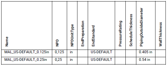
Starting with version 8.0 of 3D SymbolDesigner, value sets of piping nozzle parameters can be defined in the Config.xls file. The sets can be used like this:
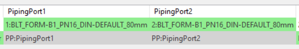
The following sheets are available to define the sets:
PipingPortsMale
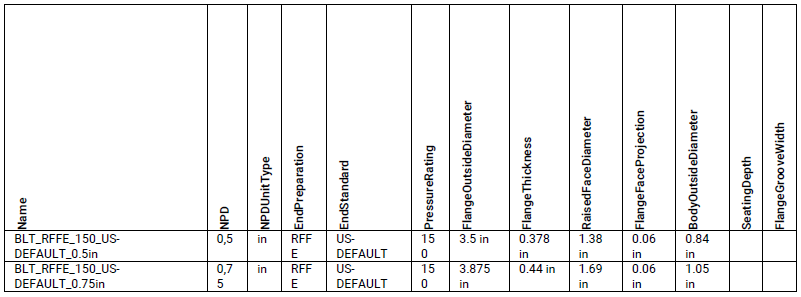
PipingPortsBolted
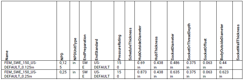
PipingPortsFemale
PipingPortsMechanical

PipingPortMapping
| Parameter | Value | CodelistValue |
|---|---|---|
| EndPreparation | 301 | |
| EndPreparation | BE | 301 |
| EndPreparation | PE | 391 |
| EndPreparation | MTE | 331 |
| EndPreparation | SWE | 421 |
| EndPreparation | FTE | 441 |
| EndPreparation | RFFE | 21 |
| EndPreparation | RFTBE | 121 |
| EndPreparation | FORM-B1 | 21 |
| EndPreparation | FORM-B1-TBE | 121 |
| EndPreparation | MJBLE | 542 |
| EndStandard | US-DEFAULT | 5 |
| EndStandard | B16.47A | 945 |
| EndStandard | DIN-DEFAULT | 100 |
Smart 3D
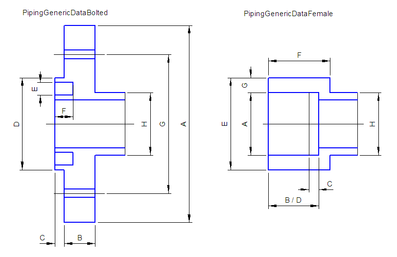
PipingGenericDataBolted
| Attribute | Remark | Must | Sketch | |
|---|---|---|---|---|
| 1 | NominalPipingDiameter | Input | X | |
| 2 | NominalDiameterUnits | Input | X | |
| 3 | PressureRating | Input, Codelist | X | |
| (3a) | (RatingPractice) | Input, Codelist PressureRating, Parent of PressureRating | X | |
| 4 | EndPreparation | Input, Codelist | X | |
| (4a) | (TerminationSubClass) | Input, Codelist EndPreparation, Parent of EndPreparation | X | |
| (4b) | (TerminationClass) | Input, Codelist EndPreparation, Parent of TerminationSubClass | X | |
| 5 | EndStandard | Input, Codelist | X | |
| (5a) | (EndPractice) | Input, Codelist EndStandard, Parent of EndStandard | X | |
| 6 | FlangeOutsideDiameter | see sketch | X | A |
| 7 | FlangeThickness | see sketch | (X) | B |
| 8 | FlangeThicknessTolerance | is required for computing bolt length | ||
| 9 | FlangeFaceProjection | see sketch | C | |
| 10 | RaisedFaceDiameter | see sketch | D | |
| 11 | FlangeGrooveWidth | see sketch | E | |
| 12 | SeatingDepth | see sketch | F | |
| 13 | BoltCircleDiameter | see sketch | (X) | G |
| 14 | QuantityOfBoltsRequired | (X) | ||
| 15 | BoltDiameter | (X) | ||
| 16 | BodyOutsideDiameter | see sketch | (X) | H |
| 17 | DrillingTemplatePattern | Codelist | ||
| 18 | BoltPatternLength | used for not circular bolted ports | ||
| 19 | BoltPatternWidth | used for not circular bolted ports | ||
| 20 | GroovePitchDiameter | used for ring type joint flanged ends only | ||
| 21 | LapThickness | used for lap joint flange without stub end (part) only | ||
| 22 | CounterBoreDepth | used for Bolt Type="Cap screw, socket head, counter bore" only | ||
| 23 | BoltPatternOffset | used for not circular bolted ports |
PipingGenericDataFemale
| Attribute | Remark | Must | Sketch | |
|---|---|---|---|---|
| 1 | NominalPipingDiameter | Input | X | |
| 2 | NominalDiameterUnits | Input | X | |
| 3 | PressureRating | Input, Codelist | ||
| (3a) | (RatingPractice) | Input, Codelist PressureRating, Parent of PressureRating | ||
| 4 | Schedule | Input, Codelist ScheduleThickness | ||
| (4a) | (ScheduleThicknessPractice) | Input, Codelist ScheduleThickness, Parent of Schedule | ||
| 5 | EndPreparation | Input, Codelist | X | |
| (5a) | (TerminationSubClass) | Input, Codelist EndPreparation, Parent of EndPreparation | X | |
| (5b) | (TerminationClass) | Input, Codelist EndPreparation, Parent of TerminationSubClass | X | |
| 6 | EndStandard | Input, Codelist | X | |
| (6a) | (EndPractice) | Input, Codelist EndStandard, Parent of EndStandard | X | |
| 7 | SocketDiameter | see sketch | X | A |
| 8 | SocketDepth | see sketch | B | |
| 9 | SocketOffset | see sketch | C | |
| 10 | ThreadDepth | see sketch | D | |
| 11 | HubOutsideDiameter | see sketch | (X) | E |
| 12 | HubThickness | see sketch | (X) | F |
| 13 | SocketWallThickness | see sketch | G | |
| 14 | BodyOutsideDiameter | see sketch | (X) | H |
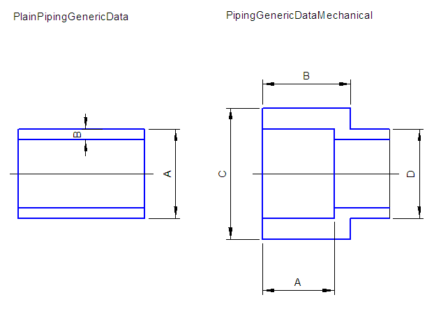
PlainPipingGenericData
| Attribute | Remark | Must | Sketch | |
|---|---|---|---|---|
| 1 | NominalPipingDiameter | Input | X | |
| 2 | NominalDiameterUnits | Input | X | |
| 3 | PressureRating | Input, Codelist | ||
| (3a) | (RatingPractice) | Input, Codelist PressureRating, Parent of PressureRating | ||
| 4 | Schedule | Input, Codelist ScheduleThickness | ||
| (4a) | (ScheduleThicknessPractice) | Input, Codelist ScheduleThickness, Parent of Schedule | ||
| 5 | EndStandard | Input, Codelist | X | |
| (5a) | (EndPractice) | Input, Codelist EndStandard, Parent of EndStandard | X | |
| 6 | PipingOutsideDiameter | see sketch | (X) | A |
| 7 | WallThickness | see sketch | B |
PipingGenericDataMechanical
| Attribute | Remark | Must | Sketch | |
|---|---|---|---|---|
| 1 | NominalPipingDiameter | Input | X | |
| 2 | NominalDiameterUnits | Input | X | |
| 3 | PressureRating | Input, Codelist | ||
| (3a) | (RatingPractice) | Input, Codelist PressureRating, Parent of PressureRating | ||
| 4 | EndPreparation | Input, Codelist | X | |
| (4a) | (TerminationSubClass) | Input, Codelist EndPreparation, Parent of EndPreparation | X | |
| (4b) | (TerminationClass) | Input, Codelist EndPreparation, Parent of TerminationSubClass | X | |
| 5 | EndStandard | Input, Codelist | X | |
| (5a) | (EndPractice) | Input, Codelist EndStandard, Parent of EndStandard | X | |
| 6 | GrooveDepth | see sketch | A | |
| 7 | GrooveWidth | see sketch | B | |
| 8 | GrooveSetback | see sketch | C | |
| (9) | Body/PipingOutsideDiameter | is used of PlainPipingGenericData | D |
Port Attributes SymbolDesigner
| Attribute | Remark | Bolted | Female | Plain | Mech | |
|---|---|---|---|---|---|---|
| 1 | NPD | Input | X | X | X | X |
| 2 | NPDUnitType | Input | X | X | X | X |
| 3 | PressureRating | Input, Codelist | X | X | X | X |
| 4 | RatingPractice | Input, Codelist PressureRating, Parent of PressureRating | X | X | X | X |
| 5 | ScheduleThickness | Input, Codelist | X | X | ||
| 6 | SchedulePractice | Input, Codelist ScheduleThickness, Parent of Schedule | X | X | ||
| 7 | EndPreparation | Input, Codelist | X | X | X | |
| 8 | TerminationClass | Input, Codelist EndPreparation, Parent of EndPreparation | X | X | X | |
| 9 | TerminationSubClass | Input, Codelist EndPreparation, Parent of TerminationSubClass | X | X | X | |
| 10 | EndStandard | Input, Codelist | X | X | X | X |
| 11 | EndPractice | Input, Codelist EndStandard, Parent of EndStandard | X | X | X | X |
| 12 | PipingPointBasis | Input PartClass, Codelist PipingPointUsage | X | X | X | X |
| 13 | ID | Input PartClass | X | X | X | X |
| 14 | PortIndex | Input PartClass | X | X | X | X |
| 15 | FlowDirection | Input PartClass, Codelist | X | X | X | X |
| 16 | FlangeOrHubOutsideDiameter | X | X | |||
| 17 | FlangeOrHubThickness | X | X | |||
| 18 | FlangeOrMechanicalGrooveWidth | X | X | |||
| 19 | FlangeProjectionOrSocketOffset | X | X | |||
| 20 | FlangeProjection | only for "Bolted" | X | |||
| 21 | LinerThicknessAtFaceOfFlange | used according to LinerThicknessData- Sheet only | (X) | |||
| 22 | LinerThicknessAtInsideDiameter | used according to LinerThicknessData- Sheet only | (X) | |||
| 23 | PipingInsideDiameter | calculated in SP3D (PipingOutsideDiameter - 2 * WallThickness) | (X) | |||
| 24 | PipingOutsideDiameter | attribute Body/PipingOutsideDiameter of GenericData | X | X | X | (X) |
| 25 | RaisedFaceOrSocketDiameter | X | X | |||
| 26 | ReinforcedWallThickness | used according to DINWallThicknessData- Sheet only | X | |||
| 27 | SeatingOrGrooveOrSocketDepth | X | X | X | ||
| 28 | SeatingDepth | only for "Bolted" | X | |||
| 29 | WallThicknessOrGrooveSetback | X | X | X |