Appendix - Custom Settings Files
In UniversalPlantViewer, there is a series of files that can be used to customize the content and the options available in the software itself. This is a detailed listing of the different file types.
Configuration File
By editing the configuration file you can hide buttons from the menu on the left, the tree bar on top of the screen and the menu on the right. Only the tab bar at the bottom cannot be hidden so that PDFs and other internal documents can be viewed and closed.
The configuration is stored in defaultConfig.upv files in the same folder as the Universal Plant Viewer.exe and can be edited using a text editor.
Keep in mind that certain elements can influence others.
Table 8: List of menu items
| Icon | Key | Description |
|---|---|---|
|
|
All | Hide the whole UI. |
| LeftMenu | Hide the complete menu on the left. | |
| RightMenu | Hide the complete menu on the right. | |
|
|
Search | Hide the search button in the right menu. |
|
|
CameraModes | Hide the camera modes. UniversalPlantViewer will use the orbit mode. |
|
|
Fit | Hide the Fit button. |
|
|
ClippingModes | Hide the clipping modes. |
|
|
ClippingModeSettings | Hide the settings for the clipping modes. |
|
|
ColourButton | Hide the button for colouring objects. |
|
|
Highlight | Hide the Highlight button. |
|
|
Measure | Hide the Measure distances button. |
|
|
ShowPackagesPanel | Hide the Open the packages panel. |
|
|
ViewPanelVisible | Hide the Open views panel button. |
|
|
ShowAvatars | Hides the Open addaitional objects panel button. |
|
|
ImportObject | Hide the Load object from disk button. |
|
|
ShowComments | Hide the Open commenting system button. |
|
|
Markup | Hide the Open markup button. |
|
|
OpenSketchMode | Hide the Open sketch mode button. |
|
|
ShowCustomAttributePanel | Hide the Custom attributes panel button. |
|
|
ToolsButton | Hide the Tools button. |
|
|
LineTracking | Hide the Activate line tracking button. |
|
|
SettingsButton | Hide the settings button. |
|
|
TreeBar | Hide the navigation bar on top. |
|
|
TreeConfiguration | Hide the Configure the project tree button. |
|
|
FileButton | Hide the file management. |
|
|
LoadColourFile | Hide the Load a colour file button. |
|
|
LoadLinkFile | Hide the Load a link file button. |
|
|
CreateReport | Hide the button to create reports. |
|
|
ExportObjects | Hide the save objects to disk button. |
Example: The following code will hide the centre, highlight and measure buttons from the menu on the left:
{
"ConfigVersion": 2,
"Views": [{
"Name": "Default View",
"HiddenMenuItems": [
"Fit",
"Highlight",
"Measure",
],
...
The configuration is separated into 4 blocks:
CurrentViewSettings: Define the default view when initially opening the UPV model or resetting
Views: Storage for all saved views
CommonSettings/UserSettings: The default upv settings can be distributed freely between those two blocks. With this you can place common settings which should apply to all users in the "CommonSettings" block. The specific user settings are supposed to be stored in the "UserSettings" block.
Blocks from multiple configurations are merged. Common settings are not saved by default.
Filters
You can define filters for setting blocks (common/user).
UPV always uses the first matching block for each unique feature. All following matches are ignored.
A “filters” block can contain multiple clauses. They are linked with an OR operator.
Example:
"CommonSettings": [
{
"Filters" : [{"DeviceType" : "IOS"}, {"DeviceType" : "Android"}],
LodTrianglesLimit": 50000000
},
{
"LodTrianglesLimit": 50000001
}
]
In this example all users with an Android or iOS device have a triangles limit of 50000000.
All other users have a triangles limit of 50000001.
Possible Filters
UserDomainName = "Caxperts01"
DisplaySize = ... options: Smartphone (<9 inch), Tablet (9 -14 inch), Desktop (14-28 inch), Large (28-40 inch), VeryLarge (> 40 inch)
DeviceType = ... options: Windows, IOS, Android, UniversalWindowsPlatform
DeviceName = ...
UserName = ...
Recap: Elements that can be predefined / added
Predefining certain elements speeds up working with UniversalPlantViewer, especially for routine tasks.
In the respective chapters you can find descriptions how to predefine:
Views
Volumes
Reports
You can add
Colour files
Link files
Object lists for creating double-sided ISOs
Autostart Files
In UniversalPlantViewer, there are a couple of default and settings files that are automatically considered on UPV start-up. These files must be named exactly as shown in the list below for the autostart to work:
| Location | Name | Function |
|---|---|---|
| .\Data\ | Links.xlsx | Linking file for external links and documents. |
| .\Data\ | IntelliPidAttributes.xlsx | definition of custom attributes to be used in IntelliPID |
| .\Data\ | IntelliPidAttributeData.xlsx | custom attribute values for IntelliPID to be loaded on UPV startup |
| .\Data\ | IntelliPidReportDefinition.xlsx | definition of reports and their filters for IntelliPID |
| .\Data\colorfiles\ | upvcolorindex.txt | listing of the default display styles to be listed in the Display Style Selection in the UPV Load display style menu. |
| .\Data\ | upvintellipidsketchitemindex.txt | Lists all catalogue items to be shown in IntelliPID Sketching. |
Link Mapping Files
There are three ways to add links to you UniversalPlantViewer model:
During the building process through a link mapping file
Automatically loading a link mapping file on start-up (Links.xlsx in the \Data\ Folder of the model)
Loading a link mapping file (see section File menu of the chapter Left side menu).
All three ways utilize the same type of definition in form of an Excel link mapping file:
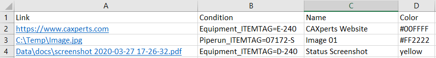
Link - The Link can be either a weblink to a website or a web-based database with according link building (row 2), an absolute path (row 3) or a path relative to the model’s root directory (row 4), which is the directory the Data folder is located in.
Condition - The Condition can be any filter (incl. wildcards) relating to an Attribute in UniversalPlantViewer.
Name - The Name is the display name of the link. This is the text that will be shown in the Attributes panel in UPV.
Colour - The colour setting can be either a hexadecimal RGB colour definition preceded by a # or one of the Excel default colours in clear name notation: black, white, red, green, blue, yellow, magenta, and cyan.
Custom Attributes
Custom attributes are user defined attributes that can be altered before each launch of UniversalPlantViewer. Their values can be changed at runtime (except calculation attributes). The Custom Attributes for IntelliPID are defined in the file IntelliPIDattributes.xlsx. This file can contain 4 worksheets (tabs):
Definition
Codelist
Filter
Meta
Worksheet “Definition”
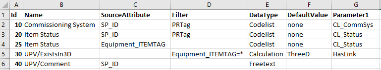 In this worksheet, the custom attributes are defined:
Id – The Id of the custom attribute can be any number. The only condition is that an Id must be unique throughout the complete custom attributes list. This Id is later used for value assignment.
Name – The name the attribute is displayed by in UniversalPlantViewer
SourceAttribute – The attribute the custom attribute
“attaches” itself to. E.g., SP_ID generates many entries since it
attaches itself to any object with the attribute SP_ID. This may
influence the performance of UPV.
It is highly recommended to use SourceAttribute as specific as
possible.
Filter – Sets a filter to assign the custom attributes only to objects covered by the filter. A filter can be directly entered here (row 5), wildcards are valid. Instead, a predefined filter can be set (worksheet “Filter”).
DataType – The data type defines which properties an attribute will have. There are three basic types:
Calculation – Defines a value that will be calculated on UPV > launch. This is the only custom attribute that cannot be altered > during runtime. For IntelliPID, only the calculation HasLink is > available (DefaultValue “ThreeD” is mandatory) that gives back a > Boolean if the object exists in 3D.
Freetext – Defines a during runtime freely editable text > attribute. Accepts all value strings.
Codelist – Defines a codelist attribute. In UPV, these > attributes are displays as a combo box, enabling you to choose > from a predefined codelist of values – see worksheet “Codelist”.
DefaultValue – The value that will be assigned to the custom attribute automatically without any manual assignment being necessary. Depending on the DataType, there are different options available:
For Calculation – Only DefaultValue “ThreeD” is available.
For Freetext – can be left blank or contain any string.
For Codelist – The default value should be a value listed in the codelist definition.
Parameter1 – This parameter gives additional parameters, depending on the DataType of the attribute:
For Calculation – Only parameter “HasLink” is available.
For Freetext – not used
For Codelist – The name of the codelist to use, see worksheet “Codelist”
Id – The Id of the custom attribute can be any number. The only condition is that an Id must be unique throughout the complete custom attributes list. This Id is later used for value assignment.
Worksheet “Codelist”
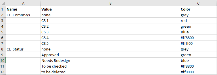 In this worksheet, the codelists for the custom attributes are
defined:
In this worksheet, the codelists for the custom attributes are
defined:
Name – The name of the codelist. This is the Name used in Parameter1 on worksheet “Definition”
Value – Defining all values available for the codelist in column A (Name)
Colour – defines the colour the respective value will be shown in in UPV. This also affects the colour used in the legend. It can be either a hexadecimal RGB colour definition preceded by a # or one of the Excel default colours in clear name notation: black, white, red, green, blue, yellow, magenta, and cyan.
Worksheet “Filter”
In this worksheet, often used filters for the custom attribute definition can be set:
Filters entered in the worksheet “Definition” are always executed separately, even if the contents of the filter strings are identical. This can slow down the loading of the custom attributes on UPV launch.
Instead, you can use the worksheet “Filter” to define a referenced filter. Filters defined here are run only once, no matter how often they are invoked on the worksheet “Definition”. Whereas a direct filter runs every single time it is invoked, using the predefined filter reuses the result of the filter, thus increasing the performance of custom attributes loading.
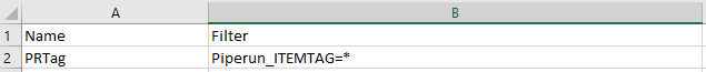
Name – The unique name of the filter to be used as reference. This name can be freely assigned.
Filter – The actual filter string as described in the worksheet “Definition”. Wildcards are allowed.
Worksheet “Meta”
In this worksheet, the parameters for the mailing of custom attribute changes can be defined:
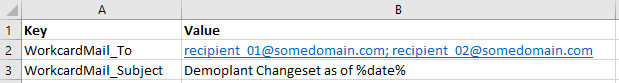
For IntelliPID, there are two keys available:
WorkcardMail_To – the recipient or list of recipients for the list of custom attribute changes.
WorkcardMail_Subject – the subject automatically added to the mail generated
Report Definitions
To define a report that will be listed in the report selection list, the file IntelliPidReportDefinition.xlsx is used. There are two ways to create a new report definition:
Definition by Copy
Create a new report and in the Report Results screen use the Copy current report definition function. This will copy the current report definition to the clipboard. Then paste the content of the clipboard to the next free row in the report definition file.
Manual Definition
You can also create a report definition manually by editing the report definition file directly:
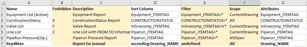
There are the following fields used to define a custom report. The fields highlighted are optional fields. They can stay empty without any impact on the functionality:
Name – The name of the codelist. This is the Name used in Parameter1 on worksheet “Definition”
Forbidden (optional) – define actions you wish to block for the report: C (customise), F (filter), or S (save). You can also combine these restrictions with comma or semicolon. Example: C,F;S
Description (optional) – Additional description to explain the purpose of the report
Sort Column – defines the column by which the report will be sorted. If no prefix is added, the report will be sorted in asceding order. Optionally, you can add a prefix ascending: or descending: before the attribute.
Filter (optional) – All attributes, including custom attributes as well as wildcards can be used for filtering.
Scope (optional) – Define the scope of P&IDs. Options are All, All Open, CurrentDrawing, and Selected.
Attributes – Attributes to be included in the report. For every additional attribute, add an antry to the first free column to the right. The number of attributes to be reported on is not limited.
There are two additional special attributes for reporting: Colour returns the current colour of the object and “Count” gives you the number of objects contained in that object. For instance, a vessel with four nozzles will have a count of five.
Display Styles
Colour List File
UniversalPlantViewer uses one central list file (upvcolorindex.txt) for the listing of available Display Styles. This file is located in the colourfiles folder of your model’s Data folder. It is automatically considered on launch. It contains the names of the colour files to be show by default in the Set display style selection in the File menu.
Colour Files
You can create custom colour files using Excel for the definition of colours, conditions and colour groups.
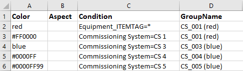
Colour – defines colours to colourise the designated items. There are two ways to define a colour:
Use Excel colours in clear name notation: black, white, red, green, blue, yellow, magenta, and cyan.
Use HTML (hexadecimal) colour codes starting with # followed by 6 digits for the basic colours plus two optional digits for opacity: #RRGGBBOO. Please note that the hexadecimal values range from 00 (decimal 0) to FF (decimal 255).
For condition you can enter a filter for any attribute or custom attribute. Wildcards are supported.
Aspect is an option for 3D colouring and is not used for IntelliPID display styles.
GroupName is an optional value by which you can define separate colour groups in one file. This enables you to define several different conditions without the need to define separate colour files. Conditions belonging to the same colour group must have the exact same group name.
Sketch Item Index File
In order to use custom sketching items a Sketch Item index file has to be created and named upvintellipidsketchitemindex.txt. This file contains the paths to the according Sketch Item files you wish to be included in your model.
A catalogue item is a pair consisting of a .svg and a .jpg or .png file, where the .svg defines the graphics of the symbol itself while the .jpg/.png file delivers the symbol preview to be shown in the catalogue.
Adding Object to the Catalogue
You can add any .svg file and a corresponding .jpg / .png file (optional) to your catalogue. UPV will include it on model launch if the object is valid and properly listed with name and path in the file Sketch Item index file. You can use absolute paths, relative paths and include:
Absolute path - C:\temp\Pumps\pump2.svg
Relative Path – IntelliPidCatalogue\Valves\valve1.svg (relative to the location of your UPV model folder)
Include - #include D:\yourindex.txt - Include can be used to manage objects for the whole company in as many files as needed, rather than adding single objects to single models. In this example yourindex.txt stands for a separate Sketch Item index file.
Deep Linking in IntelliPID
You can include deep links in all types of documents that support links, i.e. Word, websites, email … to open UniversalPlantViewer and transfer a combination of queries and commands.
Deep linking uses the URL handler upvapi://
Structure:
upvapi://<MODEL-URL>?<QUERY>&<COMMANDS>
Example:
upvapi://http://demo.universalplantviewer.com/demoPlant/6/0?Equipment%20ITEMTAG=D-240&CMD!Target=IntelliPid&CMD!OpenIntellipidDrawings&CMD!Select&CMD!Fit
This will look for the Equipment_ITEMTAG D-240, open the according drawing in IntelliPID, select the Item, highlight it and fit it to the screen.
Wildcards:
* = any character
_ = any single character
Condition Operators
By default query conditions are combined with AND:
Equipment%20ITEMTAG=K-001&Nozzle Name=N5
OR is possible with the combine command:
Equipment%20ITEMTAG=K-001&Equipment%20ITEMTAG=D-100&CMD!Combine=OR
Drawing Templates
The creation of a drawing requires the use of a drawing template. The available drawing templates are defined in the text file drawingtemplates.json which is located in the UPV model data folder: Data\drawingtemplates.
Each drawing template contains all necessary information like name, drawing border file (.svg) and the parameters of one or more drawing view(s).
The drawing border files can be located in any folder within the drawingstemplates folder.
Every drawing template needs the parameters shown in the table below.
| Parameter | Description |
|---|---|
| Name | The template name as shown in UPV |
| BorderFile | .svg file including its relative path to the folder drawingtemplates, e.g. en/EN_Metric_A1_Border_Wide.svg |
| DrawingArea | Contains the parameters of each drawing view |
| Top | The upper border of the drawing view in [mm] |
| Left | The left border of the drawing view in [mm] |
| Width | The maximum width of the drawing view in [mm] |
| Height | The maximum height of the drawing view in [mm] |
| ViewDirection | The number defines the view direction for the drawing view: FromNorth = 0, FromEast = 1, FromSouth = 2, FromWest = 3, FromTop = 4, FromBottom = 5, FromTopSouthWest = 6, FromTopSouthEast = 7, FromTopNorthWest = 8, FromTopNorthEast = 9, FromBottomSouthWest = 10, FromBottomSouthEast = 11, FromBottomNorthWest = 12, FromBottomNorthEast = 13 |
| PrintScale | Predefined fixed scale, e.g. 100 defines a 1:100 scale; 0.0 defines automatic scaling |
| Fit | If true, the maximum possible scale (e.g. 1:178) will be used, if false or missing the maximum possible standard scale (in this case 1:200) will be used. |
| UseCommonScale | true or false false means the drawing area will use the lowest possible scale for this individual drawing area The calculated and used scale will be displayed in the drawing if the .svg file has a text field marked as ###SCALE### |
Examples for two simple templates:
[
{
"Name": "EN, Metric, A1 Wide, Isometric View",
"BorderFile": "en/EN_Metric_A1_Border_Wide.svg",
"DrawingAreas": [
{
"Top": 12.0,
"Left": 22.0,
"Width": 806.0,
"Height": 515.0,
"ViewDirection": 6,
"PrintScale": 0.0,
"Fit": false,
"UseCommonScale": true
}
]
},
{
"Name": "EN, Metric, A4 Wide, Top View",
"BorderFile": "en/EN_Metric_A1_Border_Wide.svg",
"DrawingAreas": [
{
"Top": 12.0,
"Left": 22.0,
"Width": 806.0,
"Height": 515.0,
"ViewDirection": 4,
"PrintScale": 0.0,
"Fit": false,
"UseCommonScale": true
}
]
}
]
Example for multiple drawing views in a template, e.g. for an orthographic standard projection:
[
{
"Name": "EN, Metric, A3 Wide, Standard Views",
"BorderFile": "en/EN_Metric_A3_Border_Wide.svg",
"DrawingAreas": [
{
"Top": 11.0,
"Left": 21.0,
"Width": 194.0,
"Height": 110.0,
"ViewDirection": 2,
"PrintScale": 0.0,
"Fit": false,
"UseCommonScale": true
},
{
"Top": 11.0,
"Left": 215.0,
"Width": 194.0,
"Height": 110.0,
"ViewDirection": 3,
"PrintScale": 0.0,
"Fit": false,
"UseCommonScale": true
},
{
"Top": 121.0,
"Left": 21.0,
"Width": 194.0,
"Height": 110.0,
"ViewDirection": 4,
"PrintScale": 0.0,
"Fit": false,
"UseCommonScale": true
}
]
}
]
Create a Link File with Excel
You can create link files using Excel. Simply include a column for condition, link URL (or local path) and name. In thes+*+++ condition you can use all attributes. If you want to select all objects, use * as a wildcard. For example: Task=*
Example:
| Condition | Link | Name |
|---|---|---|
| Task=Piping | https://www.caxperts.com/ | Homepage |
| Task=Structure | https://en.wikipedia.org/wiki/Structure | Wikipedia |
Report Definition Files
|
|
After clicking on Create a report in File management you can choose a report definition file, or create a new report. Report definition files are Excel files that must be stored in the Data folder of your UniversalPlantViewer directory. By default, saved reports will follow this naming convention: |
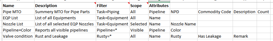
A report definition file can contain the following columns:
| Name | A descriptive name for your report. |
| Description (optional) | Additional description what your report is for. |
| Filter (optional) | You can use all attributes including custom attributes. |
| Scope (optional) | Choose “All”, “Selected” or “Visible”. |
| Column (optional) | The attribute column that should be used for sorting your report. |
| Sort (optional) | You can sort in ascending (asc) or descending (des) order. If no sorting order is given UniversalPlantViewer will sort in ascending order. Example: descending:Name |
| Forbidden (optional) | Enter actions you do not want to allow for your reports: C (customise), F (filter), S (save). Combine with comma or semicolon. Example: C,F;S |
| Attributes | Attributes your report should contain. “Colour” gives you the current colour, “Count” gives you the number of objects contained in that object. For example a vessel with 4 nozzles will have a count of 5. |