IsoOverView
For users
- Set the Debug On switch in the Schedule Batch Job screen during isometric sheet creation and start Iso as usual.

Start IOV (iov.exe)
Select the project-specific ini file
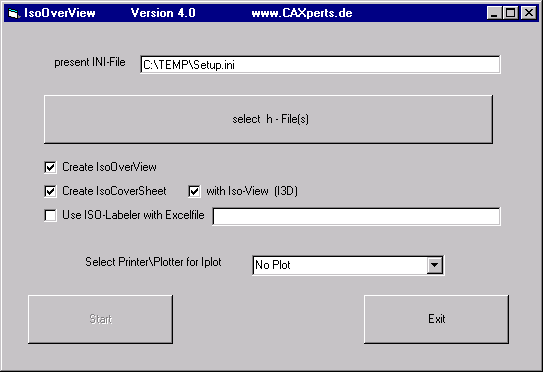
Select one or more h files (isometric sheets).
Select the plotter or printer.
Click on "Start".
Wait until Microstation terminates and the IOV message "ISO Over View completed" is displayed.
For the administrator
Automatic hits file generation
IOV requires the Hits file for each pipeline. Users can either set the Debug On switch on generation of the isomorphic sheets or word 16 can be set to 0 in INTERGRAPH_OPTIONS_BLOCK.
Program execution
Below is a brief summary of how the program executes in order to improve readers' understanding of the process.
The iov.ini file in the program folder is read
The INI file selected by the user is read
The seed file is copied to an iov file
All the elements in the iov file are set to pipelv level
The pipeline is drawn
The isometric sheet is opened
All elements on pipelv are deleted
The view mstnseedview from the iov file is referenced with the scale refscale and insertion point refpoint
The reference file is copied into the isometric sheet
The iov file is detached
The line terminal numbers are written to the IOV file
The grid file is read and the distance is calculated
The "Connnect to" information is read from the IDF file
The IsoCoverSheet is created (ICSseed copied)
The IOV file is copied in (via refernece)
The table is created
The I3D file is created
The line terminal numbers are written to the I3D file
The I3D file is copied in (via reference)
Microstation is terminated
Creation of the Seed files
Seed files are Microstation 2D files.
IsoOverView seed file
This contains the key plan drawing with the original coordinates and the Saved View with the name taken from the mstnseedview variable.
The recommended procedure for creating the seed file is as follows.
Open the PDS model (Piping or EQP) with the referenced grid.
Reference the model with the most important components.
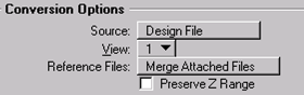
File Export 2D...
Select View: Top View.
Edit the seed file, e.g. delete any surplus lines.
Create a Saved View with the name from the mstnseedview variable.
IsoCoverSheet (ICS) seed file
This file is usually a copy of the IsoGen border file. The additional dimension table entries should also be made here.
LOG file
The Temp folder (often c:\temp) contains a LOG file (iov.log). Thanks to this file, it is easy to identify errors.
INI file
[IsoOverView]
seedfile=o:\sk\proj\lingen\defset\iovseed.dgn
pipeco=3
pipelv=40
pipewt=4
pipelc=0
'Name of the Saved view in the IOV seed file
mstnseedview=iov
'Insertion scale of the view in the Iso sheet (???.i01)
refscale=7:1
'Insertion point of the view in the Iso sheet (???.i01)
refpoint=100,35
isopath=O:\sk\proj\lingen\iso\
'Factor for unit conversion (default 1000)
Unitfactor=1000
'Elements that are not to be displayed (e.g. support segment), name from the hits file (1st column). Multiple names can be specified if separated by spaces.
NotUsedComponent=SUPP
[IsoCoverSheet]
'Color, Level, Weight, Text Height, etc. of the line terminal number in the CoverSheet top view (for ISO view, see [I3D])
LENtextco=2
LENtextlv=1
LENtextwt=1
LENtextlc=0
LENtexttx=0.2
LENtexttw=0.2
LENtextJustification=CC
'Color, Level, Weight, Text Height, etc. of the table in the CoverSheet
TABtextco=1
TABtextlv=1
TABtextwt=1
TABtextlc=0
TABtexttx=3.5
TABtexttw=2.5
TABtextft=29
TABtextJustification=LC
'Table settings (measured with reference to grid)
'Y coordinate of first line
TABlineheight=10
'Line spacing
TABlinespacing=6
'C coordinate of serial number
TABnumberpoint=15
'X coordinate of label (connection to)
TABlabelpoint=35
'X coordinate of delta x
TABXpoint=250
'X coordinate of delta y
TABYpoint=320
'X coordinate of delta z
TABZpoint=400
'Number of decimals for distance to grid lines
TABround=0
'The distance to the grid lines is multiplied by this distance
TABfactor=1000
'Coordinates read from the h file and the idf file are different, value necessary to locate the "Connected to" text
TABaccuracy=0.05
'MicroStation macro, fill in text field in ICS file. Isometric sheet ???.i01 is automatically referenced, this macro can then be used to copy out the text field
ICSmacro=o:\sk\proj\lingen\defset\icsmacro.bas
'ICS-Seed-File
ICSseedfile=o:\sk\proj\lingen\defset\icsseed.dgn
'PDS file for grid measurement. Created using PDS.
Gridfile=o:\sk\proj\lingen\defset\FW_lingen.dat
'Insertion scale for IOV in ICS file
ICSrefscale=25:1
'Insertion point for IOV in ICS file
ICSrefpoint=220,230
[Programm]
'These variables are used by the program itself.
Lizenz=338070
inifile=o:\sk\proj\lingen\defset\iov.ini
createIOV=1
createICS=1
createI3D=1
[IPlot]
'IPlot Iparm file
IParmfile=o:\sk\proj\lingen\defset\plotseed.i
'Printer in format: \\server\drucker
IPlotque1=\\XNS178\ls802_A3
IPlotque2=\\XNS178\ls802_A4
IPlotque3=\\S_MT200\5000A4Q
[I3D]
'3D mstnfile as seed file for isometric view
I3Dseedfile=o:\sk\proj\lingen\defset\I3Dseed.dgn
'Insertion scale for IOV in ICS file
I3Drefscale=2.2:1
'Insertion point for IOV in ICS file
I3Drefpoint=450,320
'Color, Level, Weight, Text Height, etc of line terminal numbers or isometric view
I3DLENtextco=2
I3DLENtextlv=1
I3DLENtextwt=1
I3DLENtextlc=0
I3DLENtexttx=2
I3DLENtexttw=2
I3DLENtextJustification=CC
Variables in the IsoOverView section
Seedfile
Specifies the seed file for IOV (e.g.: EQP top view exported to a 2D file).
Pipeco
Color number of the drawn pipeline.
Pipelv
Level of the drawn pipeline.
All Microstation elements on this level in the isometric sheet are deleted.
Pipewt
Line weight of the drawn pipeline.
Pipelc
Line type of the drawn pipeline.
DelLevel
Deletes all elements on this level. This is useful if the level has been changed during testing.
Specify as usual in MicroStation (e.g. 10,12,50-60)
Mstnseedview
Name of the Saved View in the IOV seed file
Refscale
Scaling for referencing the IOV file in the ISO sheet.
Refpoint
Insertion point for the IOV file in the ISO sheet.
isopath
The software itself enters the value of this variable.
Unitfactor
Factor for unit conversion (default 1000)
NotUsedComponent
Elements that are not to be displayed (e.g. support segments), name from the hits file (1st column). You can specify multiple names as long as they are separated by spaces.
Variables in the IsoCoverSheet section
LENtext??
Color, level, weight, text height etc. of the line terminal number in the CoverSheet top view (for the ISO view, see [I3D])
TABtext??
Color, level, weight, text height etc. of the table in the CoverSheet
TABlineheight
Table settings (measured with reference to the grid). Y coordinate of the first line (line height)
TABlinespacing
Table settings (measured with reference to the grid). Line spacing.
TABnumberpoint
Table settings (measured with reference to the grid). X coordinate of the serial number.
TABlabelpoint
Table settings (measured with reference to the grid). X coordinate of the label (Connected to.)
TAB?point
Table settings (measured with reference to the grid). X coordinate of delta X, delta Y or delta Z
TABround
Number of decimal places for distance to grid lines.
TABfactor
The distance to the grid lines is multiplied by this factor.
TABaccuracy
Coordinates from the h file and the idf file are different. This value is necessary to identify the "Connection to" text.
ICSmacro
MicroStation macro, fill in text field in the ICS file. Isometric sheet ???.i01 is automatically referenced. This macro can be used to copy out the text field.
ICSseedfile
ICS seed file.
Gridfile
The PDS file for grid measurement. This is created using PDS.
ICSrefscale
Insertion scale for IOV in the ICS file.
ICSrefpoint
Insertion point for IOV in the ICS file.
gridextension
Excess grid. The terminal point may lie outside the grid if still within this value. This is of value if multiple grids are in use.
If this value is not specified then the terminal point may be located at any distance from the edge of the grid.
Variables in the Programm section
Lizenz
You enter the licence number here. The licence number is supplied by ITC-Schlegel. The licence applies to the entire domain, i.e. you can use the program throughout the entire network.
INI-File
The value of this variable is entered by the software itself.
Variables in the Iplot section
Iparmfile
This variable specifies the Iplot-Iparm file.
IPlotque1 to Iplotque5
These variables make it possible to specify up to 5 plotters or printers. These are then listed in the drop-down list box.
Variables in the I3D section
I3Dseedfile
3D mstnfile as the seed file for the isometric view.
I3Drefscale
Insertion scale for IOV in the ICS file.
I3Drefpoint
Insertion point for IOV in the ICS file.
I3DLENtext??
Color, level, weight,text height etc. of the line terminal number for the isometric view.
Tools
b DGN Find and Replace
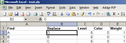
DGNFindReplace is a tool to find text in DGN files and replace the text with desired text defined in one Excel sheet.
In following example sheet, the text ‘A’ in level 6, with color 0 and weight 1 will be replaced with text ‘O’.
One can define a folder, where the DGN files will be searched with given extensions. And one can also add the desired DGN files to the file list to process them.
The Excel configuration file can be created manually, or can be created automatically using “Extract text to Excel” function.
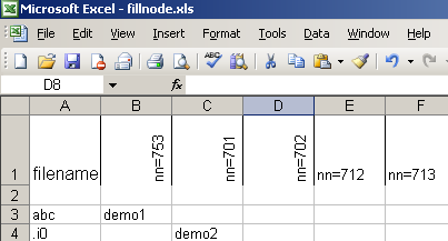
DGN Fill Text Nodes
DGN FillNode is a tool to fill DGN file text nodes with text defined in one Excel sheet.
In following example Excel sheet, all files, whose names contain substring ‘abc’, will be filled with text ‘demo1’ for text node number 753. All files, whose names contain substring ‘.i0’ will be filled with text ‘demo2’ for text node number 701.