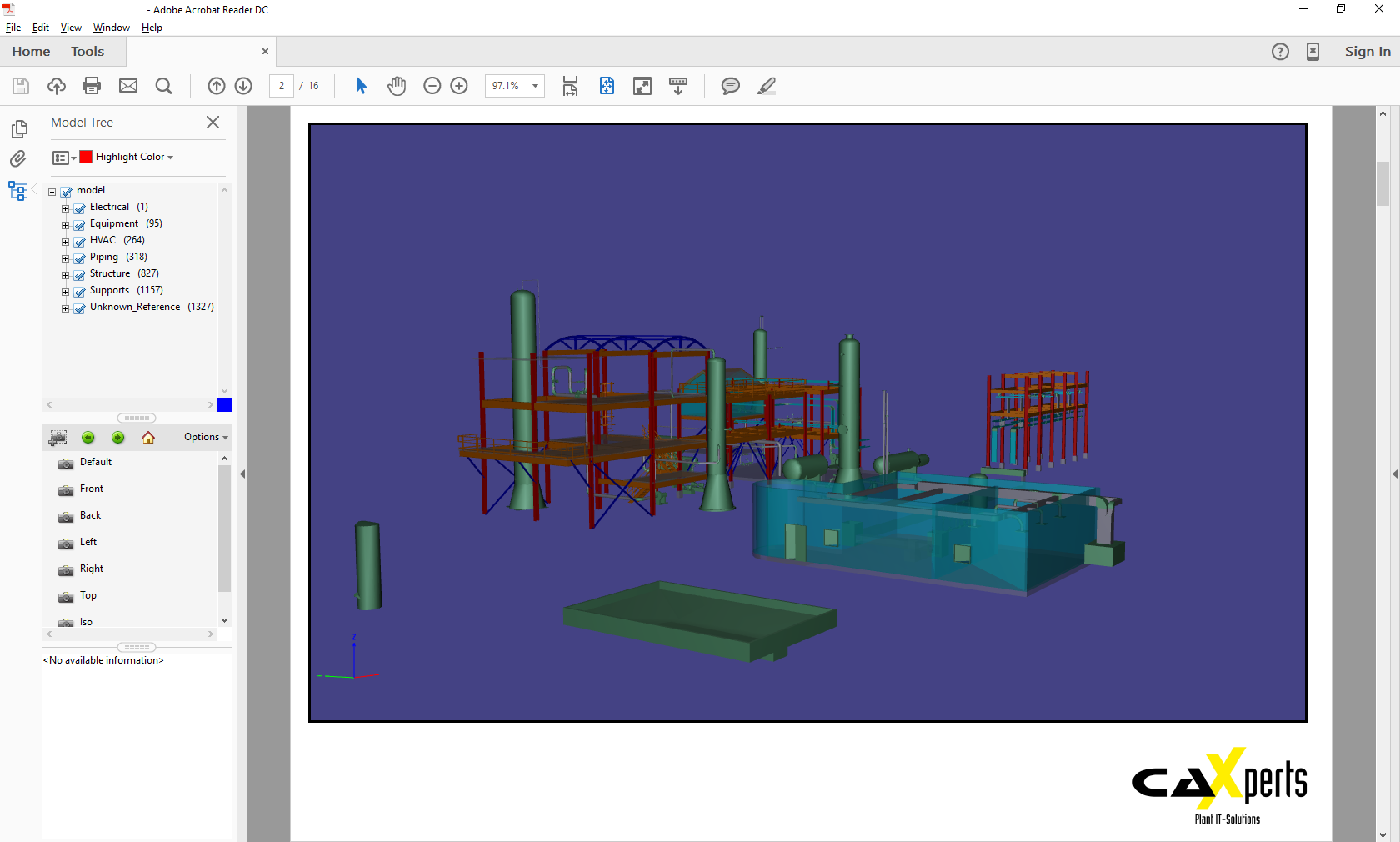
How to Use 3D PDF Files
The 3D PDF file created by Universal Plant Viewer Builder can be opened with Adobe Reader.
3D Toolbar
Display and Hide 3D Toolbar
![]()
- Click on the 3D model with the Hand tool to show the 3D toolbar.
The 3D toolbar always appears in the area above the upper left corner of the 3D model and cannot be moved.
Hide the toolbar by right-clicking the 3D model and choosing Hide toolbar. To show the toolbar, choose Show toolbar from the same context menu.
You can expand and collapse the display of 3D tools on the toolbar using Tools → Expand/Collapse 3D tools on the context menu.
All tools that can be used from the 3D toolbar can also be used by right-clicking the 3D model and using the different items of the context menu.
Use 3D Navigation Tools
- Rotate
(
 ):
):
Turn 3D objects around relative to the screen. How the objects move depends on the starting view, where you start dragging and the direction you drag, such as in a straight line or in curves, circles, or loops.
You can also use the Hand tool to select an object if Enable selection for the hand tool is selected in the 3D preferences.
- Spin
(
 ):
):
Turn a 3D model in parallel to two fixed axes in the 3D model, the x-axis and the z-axis.
- Pan
(
 ):
):
Move the model vertically and horizontally only. You can also pan with the Hand tool: Ctrl-drag.
- Zoom
(
 ):
):
Move you toward or away from objects in the scene when you drag vertically. You can also zoom with the Hand tool by holding down Shift as you drag.
- Walk
(
 ):
):
Pivot horizontally around the scene when you drag horizontally; move forward or backward in the scene when you drag vertically; maintain a constant elevation level, regardless of how you drag. The Walk tool is especially useful for architectural 3D models.
- Drag the right mouse button to change the way several of the 3D navigation tools work:
For the Rotate and Spin tools, right-click dragging temporarily shifts to the Zoom tool.
For the Zoom tool, it makes the tool function like a Marquee zoom tool, zooming to the area that you define when you drag.
For the Walk tool, right-click dragging makes the tool function as the Pan tool.
Use 3D Toolbar View Controls
- Default view
(
 ):
):
Return to a pre-set zoom, pan, rotation, and projection mode of the 3D model.
- Views menu:
Select the different views defined for the current 3D model.
- Toggle model tree
(
 ):
):
Open and hide the model tree.
- Projection
(
 ):
):
Toggle between using perspective and orthographic projection of the 3D object.
An orthographic projection effectively removes a dimension, preserving the size ratio between objects but giving the 3D model a less realistic appearance.
- Model render mode menu
(
 ):
):
Select the different model render modes to see how the 3D shape appears. Have a look on the differences in rendering speed and quality.
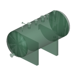
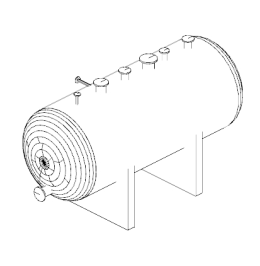
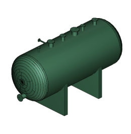
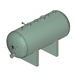
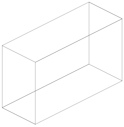
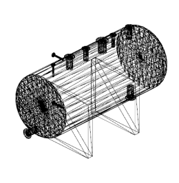
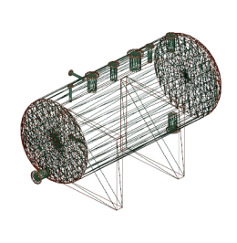
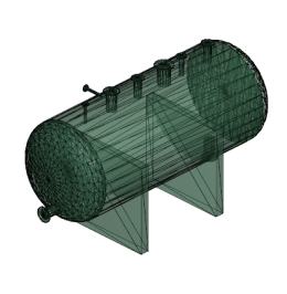
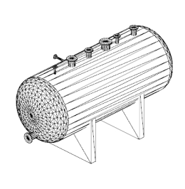
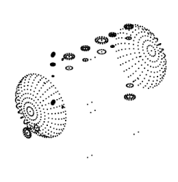
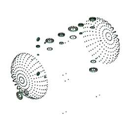
The model rendering modes include combinations of factors that affect the appearance of the 3D object. The illustration below shows a simple tank object rendered in each of the available modes. The default rendering mode is usually solid.
Table 1: Model rendering modes
| A. Solid | B. Transparent Bounding Box | C. Transparent |
|---|---|---|

|

|
|
| D. Solid Wireframe | E. Illustration | F. Solid Outline |

|
|
|
| G. Shaded Illustration | H. Bounding Box | I. Transparent Bounding Box Outline |
|
|

|
| J. Wireframe | K. Shaded Wireframe | L. Transparent Wireframe |
|
|
|
| M. Hidden Wireframe | N. Vertices | O. Shaded Vertices |
|
|
|
- Enable extra lighting menu (
 ):
):
Use the different lighting effects, to see how the number, colour, orientation, and brightness of the lights, the reflectivity of the surface, and other factors affect the illumination of the 3D object.
- Background colour swatch:
Open the colour picker, which you can use to select a different colour for the space surrounding the 3D object.
- Toggle cross section
(
 ), (not
available in Adobe Reader):
), (not
available in Adobe Reader):
Show and hide cross sections of the object. Click the pop-up button to open the Cross section properties dialog box.
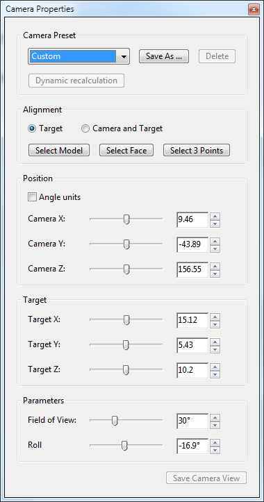
- Camera properties
(
 ):
):
Open the camera properties window and modify the camera’s position. Save camera view is not available in Adobe Reader.
Model Tree
Display and Hide Model Tree
- Open the model tree by clicking the Toggle model
tree button
() on the 3D
toolbar, or by right-clicking the 3D model and choosing Show
model tree.
The model tree appears in the navigation pane on the left side of the work area.
The model tree has three panes (structure pane, view pane, object data pane), each of which displays a specific type of information or controls.
Use Structure Pane
The topmost pane shows the tree structure of the 3D object which is composed of individual parts. For example, a 3D object depicting a storage tank may have separate groups of objects (called nodes) for the tank, insulation, and nozzles.
To configure the model tree and attributes in the PDF file, please see the section 3D PDF settings.
Move through the hierarchy and see how the related parts in 3D model are selected by selecting the tree nodes
Hide various parts, to isolate others, by removing checkmarks next to them.
Highlight, view or modify the 3D model content at any level within the model tree by right-clicking the node and selecting the desired function.
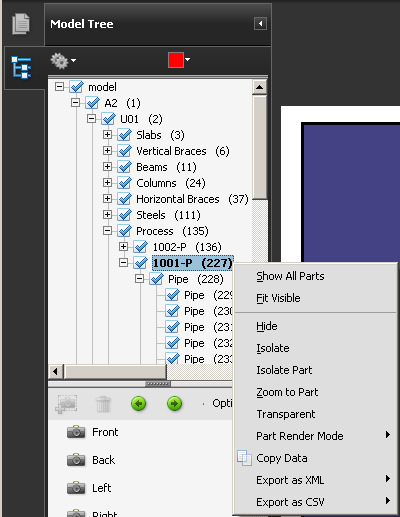
- Select the Options menu and choose any of the following:
Model render mode: Changes the surface appearance of the entire 3D model according to the item you choose from the submenu: Transparent Bounding Box, Solid, Transparent, Solid Wireframe and so on.
Show all parts: Displays the entire 3D model.
Fit visible: Displays all visible parts and centres them in the view.
Display bounding box: Displays the box that encloses the 3D object or selected parts of the model.
Set bounding box colour: Changes the colour of the bounding box. Choose this option, select a colour, and then click OK.
Hide: Displays the model without showing the selected parts.
Isolate: Displays only the selected part, hiding all others.
Zoom to part: Changes the centre focus from the entire 3D model to the selected parts. This setting is especially useful for rotating a part, allowing the rotation to occur around the part’s centre focus rather than that of the entire model.
Transparent: Displays a see-through version of the selected part.
Export as XML: Creates a separate XML file of either whole tree or current node of the 3D model.
Use View Pane
The middle pane lists the views that the document author has defined for that 3D object.
After you changed the view, such as by isolating and rotating a part, simply click one of the listed views to return the 3D model to a saved state.
Change the default view (
) of
3D toolbar view controls by right-clicking a view in
the View pane and then choosing Set as default
view
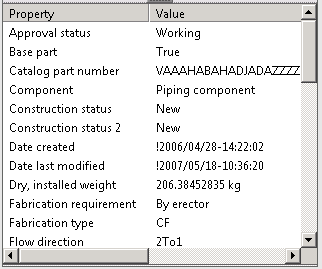
Use Object Data Pane
The lower pane displays other information, including properties and metadata, if any, about the object or part.
- Click on a particular object in the 3D view. The object data pane is filled-in automatically with the properties of the selected object (SmartPlant Review properties).
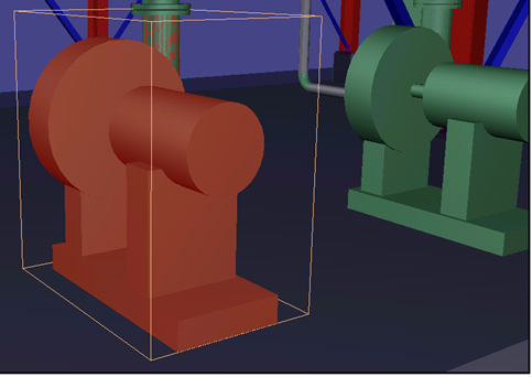
The selected object is highlighted in a bounding box and the attributes are shown on the object data pane:
Volume Clipping
3D PDF files created by CAXperts Universal Plant Viewer contain a volume clipping feature.
- Use the context menu on a 3D object in Acrobat Reader and click CAXperts - Volume clipping.
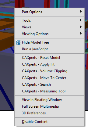
Then input the volume clipping radius around the selected object:
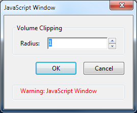
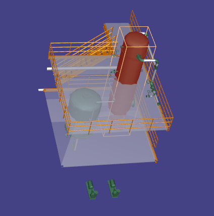
- Finally, press OK and only the selected object and all objects within the specified radius will be visible.
To switch off volume clipping, click on CAXperts - Reset model on the context menu.
Measure with CAXperts - Measuring Tool
Use the context menu on a 3D object in Acrobat Reader and click CAXperts - Measuring tool to measure 3D models.
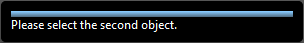
Click on the first object after this message shows up:
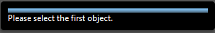
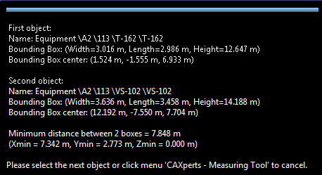
- Then click on the second object:
The distance between the centres of the bounding boxes will be shown:
Link 2D Objects with 3D Objects
The function to link 2D objects with objects of the 3D model is only available in PDF documents created with CAXperts tools.
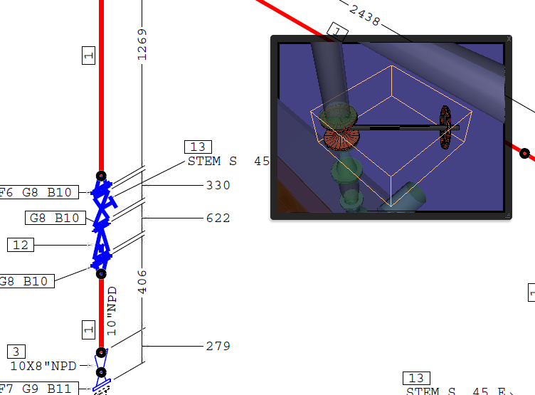
Show the 3D model in a floating window by right-clicking the 3D model and choosing View in floating window.
Click on a linked item of the 2D drawing to let the 3D window show the item’s 3D representation.
Links are obvious from the mouse pointer switching to hand whenever you hover over a link.
3D Models in Acrobat Professional
Measure 3D Objects
- Use the 3D measurement tool to measure 3D models.
You can create measurements between combinations of points or edges of the 3D model.
- Move the pointer over the 3D model to highlight specific points and edges.
The 3D measurement tool supports four types of measurements:
perpendicular distance between two straight edges,
linear distance between two points,
the radius of circular edges, and
the angle between two edges (or three points).
You can also display comments while taking measurements. However, these comments (also called measurement mark-ups) are not preserved after the document is closed.
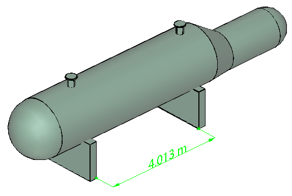
Figure 1: 3D measurement display
Click a 3D model in a PDF to enable it.
Click the 3D measurement tool icon (
 ) on the 3D toolbar. (If the
3D toolbar view is set for consolidated tools, the 3D
measurement tool is available on the pop-up menu under the
Rotate, Spin, Pan,
Zoom, or Walk tool.)
) on the 3D toolbar. (If the
3D toolbar view is set for consolidated tools, the 3D
measurement tool is available on the pop-up menu under the
Rotate, Spin, Pan,
Zoom, or Walk tool.)Select the options you want in the Snap enables, Measurement types, and Units and mark-up settings areas of the 3D measurement tool palette.
Under Units and mark-up settings, change the options, as needed. Leave the 3D measurement tool palette open.
Measure the 3D model:
To measure the distance between two positions on the 3D model, click to set a start point and move the pointer to another location or an edge.
To measure the circumference of a round shape, move the pointer to the edge of the shape so that a circle appears, and click once.
To create and set the position of an annotation on the measurement, select Measurement mark-up in the 3D measurement tool palette and then type a mark-up message in Annotation. Measure the 3D model as described above, but click to set the end point for the measurement and then click a third time to set the location of the measurement and annotation text.
To discontinue a measurement, right-click and choose Cancel measurement.
To delete a measurement mark-up, click it with the 3D measurement tool and press Delete.
Snap enables options in the 3D measurement tool palette:
3D snap to edge endpoints (
 ): Snaps to the entire
edge.
): Snaps to the entire
edge.3D snap to linear edges (
 ): Snaps to
a straight-line segment of an edge.
): Snaps to
a straight-line segment of an edge.3D snap to radial edges (
 ): Snaps to
a circumference.
): Snaps to
a circumference.3D snap to silhouettes (
 ): Snaps to
the apparent edge of a part, such as the side of a cylinder.
): Snaps to
the apparent edge of a part, such as the side of a cylinder.3D snap to planar faces (
 ): Snaps to
the geometric plane making up a face of the part.
): Snaps to
the geometric plane making up a face of the part.
Measurement types options in the 3D measurement tool palette
3D point to point measurement (
 ): Measures
the distance between two positions on the 3D model that you click to set
a start point and then click another location to set an end point or
edge.
): Measures
the distance between two positions on the 3D model that you click to set
a start point and then click another location to set an end point or
edge.3D perpendicular dimension (
 ): Measures
the distance between two edges taken at a right angle to the starting
edge.
): Measures
the distance between two edges taken at a right angle to the starting
edge.3D radial dimension (
 ): Measures
the radius at the location clicked.
): Measures
the radius at the location clicked.3D angle measurement (
 ): Measures
the angle between two edges.
): Measures
the angle between two edges.
Units and mark-up options in the 3D measurement tool palette
Model units scale ratio: Shows the relationship between units in the model and real object measurements. Use the Display units menu to select a different unit for the real object measurements.
Measurement mark-up: Select to have the measurements appear as comments in the PDF.
Label: Type text that you want to appear with the measurement, both in the 3D model area and in the comments panel. (Not available if Measurement mark-up is not selected.)
3D Measurement tool viewing options
Use the Options menu in the 3D measurement tool palette to set viewing options.
Show details: Shows or hides the Cursor location and Units and mark-up settings options in the 3D measurement tool palette.
Show rulers: Shows or hides vertical and horizontal rulers on the page. (Has the same effect as choosing View → Rulers.)
Snap to 2D content; Ensures precise measurement in 2D objects.
Snap to 3D content: Ensures precise measurement in 3D objects.
3D measurement navigation tips: Opens a dialog box with keyboard shortcuts for several 3D features. You can use these shortcuts while you are measuring.
Measuring Preferences
Change the 3D measuring preferences to determine how 3D data is measured. These options appear in the Measuring (3D) panel of the Preferences dialog box.
Use scales and units from model (when present): Displays measurements based on the model units, if present, generated from the original 3D model. Deselect this option to specify the units of measurements manually. This setting can be changed in the 3D measurement tool palette.
Use default display unit: Uses units of measurement that you specify here rather than those in the 3D model.
Significant digits to display: Specifies the maximum number of digits in the measurement number.
3D measuring line colour: Specifies the colour of the line that appears when you click or drag to measure an object.
Measure feedback size: Sets the text size for the measurement display.
Angular measurements shown in: Specifies units as either degrees or radians.
Circular measurements shown as: Designates whether the diameter or radius is measured for circular parts.
3D snap settings: Turns on snap and specifies whether points, arcs, edges, silhouette edges, or faces are snapped to. Sensitivity indicates how close the pointer needs to be to the item being snapped to. For Snap hint colour, specify the colour of the snap line that appears when you hold the pointer over the 3D object.
Comment on 3D Designs
Comments added to a 3D object are associated with specific views that are defined when the comments are added.
If the view is changed—for example, if the 3D object is rotated or moved—the comments are no longer visible.
If you don’t want a comment to be associated with a 3D view, add the comment to another part of the page, outside the 3D object area.
Add comments to a 3D object
- Select a tool from the “Comment & mark-up” toolbar.
- Click inside the 3D object area to create a new comment and also a new view definition in the model tree with a default name such as “CommentView1.”
To add more comments, do one of the following:
To create an additional comment in a view, make sure that the commenting view you want is selected in the Model Tree, and click inside the 3D object area.
To create an additional comment in a new commenting view, make sure that no commenting view is selected in the Model Tree, and click inside the 3D object area.
Display Comments for a 3D Object
Do one of the following:
In the model tree, select a view that contains comments.
Click the Comments button or choose View → Navigation panels → Comments.
In the view pane of the model tree, click Options and choose List comments.
Double-click a comment to open its comment window.
Run a JavaScript
If there is a separate JavaScript file associated with the 3D model PDF, you can activate it.
- Right-click the 3D model in the PDF, and choose Run JavaScript.
Acrobat 3D Preferences
In the 3D panel of the Preferences dialog box (Edit → Preferences) you can determine whether the 3D toolbar and model tree are displayed by default. You can also specify a default renderer and determine whether animations are allowed.
Preferred renderer: Specifies the rendering engine used to affect both performance and quality, so it’s important to select the appropriate renderer. If you select a DirectX or OpenGL option, all rendering takes place using the graphics chip on the video card. If Software is selected, rendering may take more time, but the performance may be more consistent with that of the model in its original application.
Enable double-sided rendering: Some model parts have two sides. To save time and space, you can deselect this option to render only the side facing the user. If the user looks inside a part rendered with only one side, the backside would be invisible.
Enable hardware rendering for legacy video cards: Forces the use of a hardware accelerator for even video cards that do not support a pixel shader.
Open model tree on 3D activation: Determines whether the model tree is displayed when the 3D model is activated. Choose Use annotation’s setting to use which ever setting the author used when adding the 3D model to the PDF.
Default toolbar state: Determines whether the 3D toolbar is shown or hidden when a 3D model is activated. Choose Use annotation’s setting to use which ever setting the author used when adding the 3D model to the PDF.
Enable 3D selection for the hand tool: Lets the user select and highlight parts of the 3D model using the Hand tool. If this option is not selected, use the Object data tool (Tools → Object data → Object data tool) to select the object.
Consolidate 3D tools on the 3D toolbar: Selecting this option places the manipulation and navigation tools under the Rotate tool, there by shortening the 3D toolbar.
Enable view transitions: Some 3D models include animated transitions between views. Deselect this option if you want to prevent this 3D animation.
Optimization scheme for low frame rate: Specifies what happens to animations of complex models when the frame rate becomes low.
None: does not compromise the visuals and leaves the frame rate low.
Bounding box: shows the three-dimensional planes enclosing the parts instead of the parts themselves, which keeps the frame rate high.
Drop objects: does not show some parts of the model in order to keep the frame rate high.
Frame rate threshold: Sets the minimum frame rate, either by dragging the slider or entering a number in the value box. If the frame rate drops below that number of frames per second, the Optimization scheme for low frame rate option goes into effect.