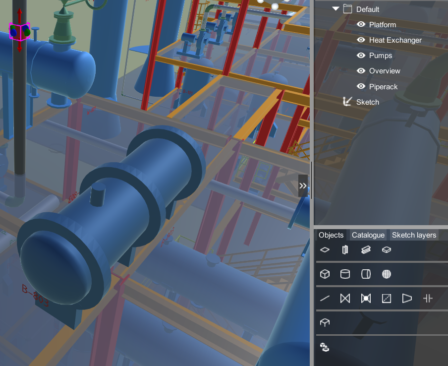
Sketch
|
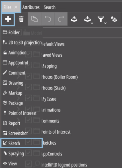
Click on “Files”,“Add” and then select
“Sketch”. This allows you to add a new sketch layer to your model, where you can add custom objects that won’t directly affect your model but can be easily positioned in relation to it. |
| Button | Description |
|---|---|
|
|
“Delete” the selected sketch item. |
|
|
Convert 3D view objects to sketch items, hiding the source object, or clone them, keeping the originals visible. During converting or cloning, you’ll be prompted to choose between referencing or copying.
|
|
|
Undo the last change to the tree. |
|
|
Redo the last undone change to the tree. |
Adding and Editing Objects
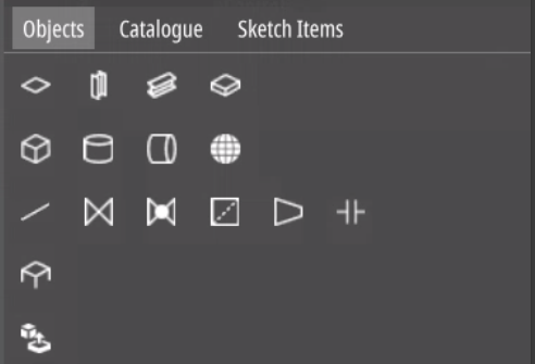
To add an object, start by selecting it from the menu on the right. Once selected, you can simply drag and drop it into position.
|
There are five object categories: |
|---|---|
|
|
|
|
|
|
|
|
|
You can still use the standard functions in the left menu. Plus,
with the sketch tab menu, you can manipulate the selected object
further.
Example
Basic Structures and Shapes
Basic structures and shapes have a default scale and custom editing possibilities in accordance with their function:
| Object | Default scale | Scaling options | Property to choose from |
|---|---|---|---|
| Ground plate | 10 x 10 m | X, Y & Z | - |
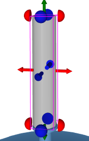
| Column | 0,3 x 0,3 x 3 m | Height only | Profile type |
| Steel | 0,05 x 0,05 x X m | Length only | Profile type |
| Slab | 1 x 1 x 0,2 m | X, Y & Z | - |
| Cube | 1 x 1 x 1 m | X, Y & Z | - |
| Sphere | 0.1 m | Z | - |
| Vertical / horizontal equipment | 2 x 1 m | X, Y & Z | - |
| Pipe | 1 m, DN 50 | Length only | Length and diameter |
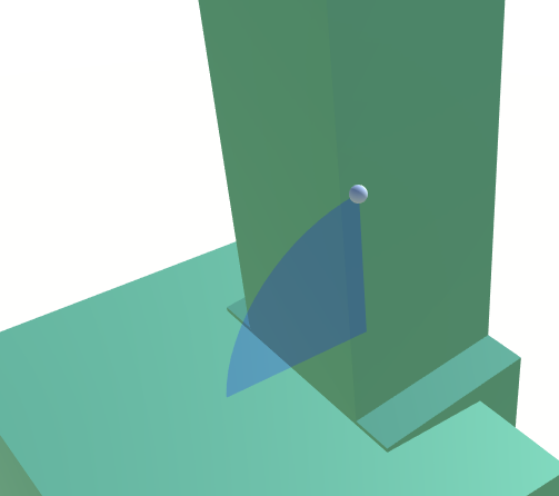
Scaling Objects in Dependence to Others
|
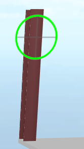
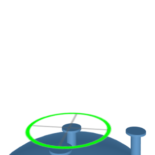
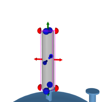
If you want an object’s measurements to match the position of another object, select the object, click on the scale icon and then click and hold one of the semi-spheres on the object you have selected. When you now move your mouse pointer over another object in your model, a green circle with crosshairs in it will appear. The crosshairs indicates the X, Y and Z coordinate where the scaling will end. |
Piping
|
|
When placing a pipe you’ll automatically get some extra options that allow you to create a pipe run and connect it to other pipes or Symbol Designer objects with Pipingconnectors. |
|
The pipes diameter can be chosen from a drop-down list in the properties. |
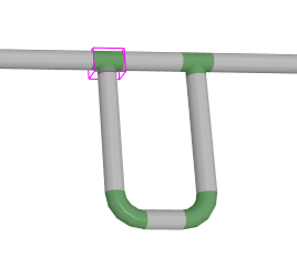
| You can add a 90° angle to the end of your pipe run by dragging the half-sphere and move / lengthen your pipe by dragging the coloured arrows. | |
| In the rotation mode, you can drag the curved arrows to change the angle of the pipe. Pressing CTRL makes the pipe-end angle towards the mouse position. |
Creating a Pipe Run
| The easiest way to create a pipe run is to click to where your pipe should start. | |
|
|
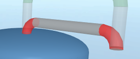
This will add a horizontal or vertical pipe depending on the orientation of the surface. By dragging one of the semi-spheres, you can continue the pipe with a 90° angle connected by a bend.
You need enough space for a bend. Otherwise bends will be displayed in red.
|
You can add additional pipes between bends or loop pipes back on themselves. |
Moving and Deleting Pipes
If you select a pipe, you can move it by dragging the directional arrows.
If you want to delete a pipe you will be asked if you want to delete the section or all connected sections, too.
Adding Piping Equipment
Valves etc. can only be added to pipes that are sketch items. Select a piece of equipment and click on the part of the pipe where you want to place it. After that you can move it to the desired place on the pipe.
Platforms
|
|
Start by placing the platform. Click on the Platform icon and then on any place in the model or drag the button into the 3D space. |
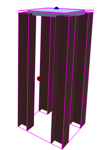
To select the whole platform, select any part of it and click on the selected part another time.
The Platform can be moved and scaled as a whole, but its columns and slabs can also be moved, scaled, and changed independently.
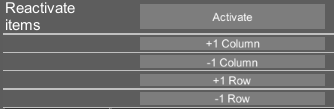
The platforms attributes have buttons to increase/decrease columns and rows. ‘Deleted’ platform objects can be reactivated with the ‘Activate’ button. You cannot reactivate single objects; unnecessary parts need to be deleted again.
Custom Objects
Custom objects in the .obj format can be placed like other “Sketch Items”. Click the button and select the object to be created from the file browser.
Adding Objects from the Catalogue
When loading a model, UPV looks for a “Catalogue” folder with subfolders for objects (i.e. Architectural). The “Catalogue” folder must be in the same folder as the Data folder.
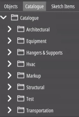
The UPV “Catalogue” includes .obj or .xls files with corresponding .jpg or .png images. Found in the Data folder of your model, the upvsketchitemindex.txt list file contains all available items. The default “Catalogue” features common plant parts like pumps and vessels, available as regular objects. While objects can be scaled, only parametric symbols maintain correct proportions
Adding Objects to the Catalogue
To expand the UPV “Catalogue”, add any .obj file along with an optional .jpg or .png image. UPV automatically includes these items during model loading if valid and properly listed in the upvsketchitemindex.txt file. Both absolute and relative paths, including #include, are supported.
Example:
Catalogue/Ladder/ladder1.obj
/Ladder/ladder2.obj
#include D:\yourindex.txt
Using #include, objects can be stored in multiple locations as required. The included text file functions similarly to the upvsketchitemindex.txt and can also contain additional includes.
The creation of a upvsketchitemindex.txt file can be automated by creating a .bat file with the following lines of code:
@echo off
for /f "delims=" %%i in ('CD') Do set wdrive=%%i
Setlocal EnableDelayedExpansion
if exist upvsketchitemindex.txt del upvsketchitemindex.txt
for /r %%a in (*.obj,*.xlsx) do (
SET out=%%a
rem set out=!out: =%%20!
set out=!out:d:\_DemoPlant\__work\20_config\=!
rem set out=!out:\=/!
set out=!out:%wdrive%=Catalogue!
echo !out! >> upvsketchitemindex.txt
)
Executing this batch file in the root folder of the catalogue that contains all subfolders and objects will delete any existing upvsketchitemindex.txt file and create a new one containing all *.obj and all *.xlsx files in all subfolders.
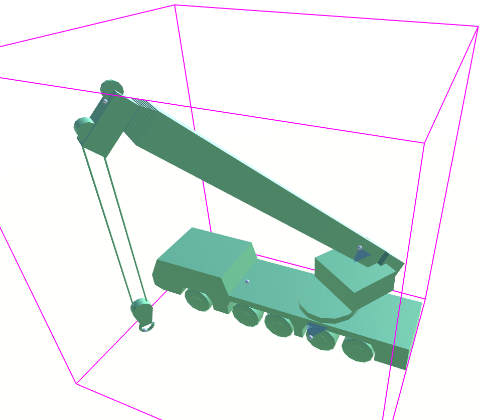
Adding Parametric Symbols to the Catalogue
Parametric symbols are created using 3D SymbolDesigner.
These symbols can contain attributes changing the looks of an object, to the point where complex objects, such as the car-crane below, with movable parts can be designed.The white spheres in the images are movable parts and can be dragged to change certain attributes in a symbol, leading to eg a rise of the crane. For an in-depth explanation on how to create symbols, please consult the 3D SymbolDesigner manual.
To add parametric symbols to the catalogue, add the respective .xlsx file created by the SymbolDesigner to the upvsketchitemindex.txt, eg:
Converting Objects from the 3D Model
In this example, we will move a tank and connect it to a pre-existing pipeline.
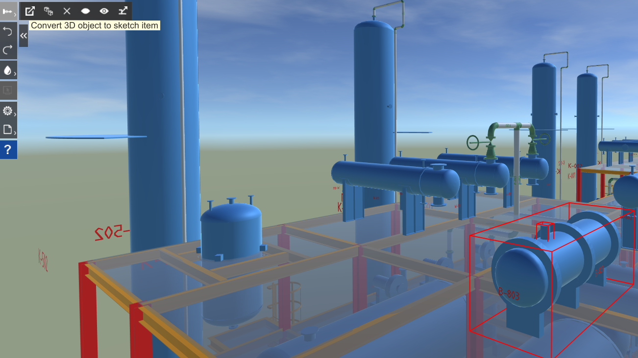
Select the tank and its nozzles and open the “Convert” menu. Click the first button “Convert 3D object to sketch item”, choose reference since the actual tank is to be moved.
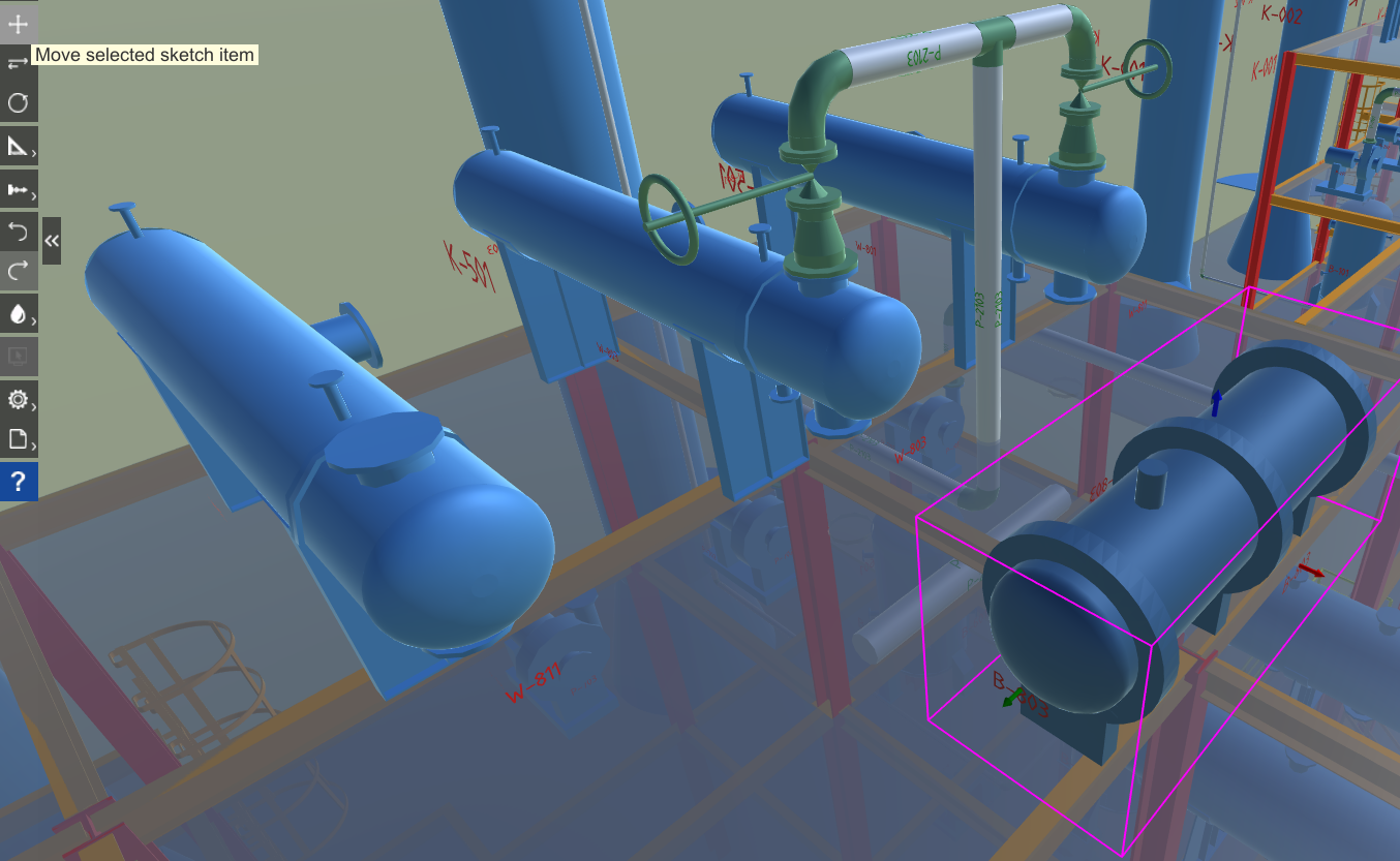
Click the button “Move” and drag the red/green arrows until the tank is next to the pipeline.
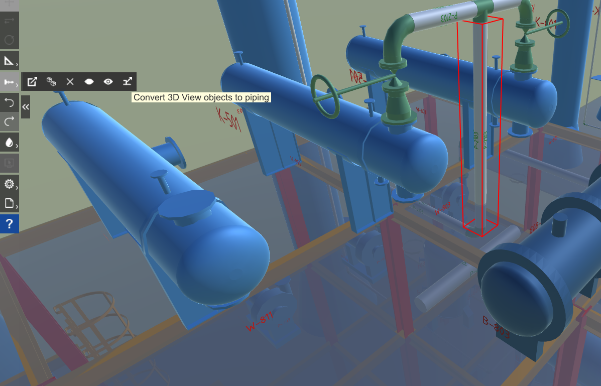
Select the pipeline you want to connect to the tank, open the “Convert” menu and click the last button “Convert 3D View objects to piping”.