Settings
Settings
|
|
UPV “Settings” offer an abundance of configuration options, providing numerous opportunities for customization. |
3D Layers
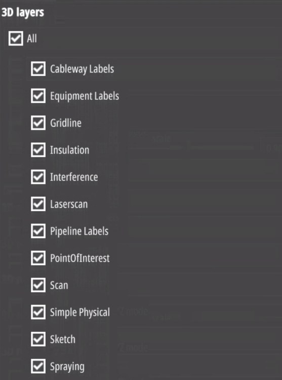
You can show or hide selected objects.
Attribute Options
Units
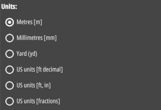
Choose the unit to be displayed when measuring or adding objects.
This does not apply to the attribute’s information.
3D User Interface
(navigation and drawings)
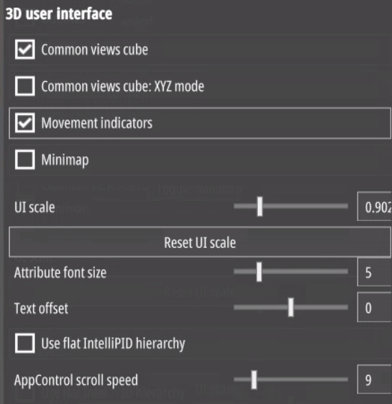
Common views cube shows/hides the navigation cube in the upper right corner in the 3D view.
Minimap shows/Hides the minimap in the bottom right corner of the 3D view.
2-sided ISO perspective chooses the side the 2-sided ISOs will face.
Use Common Views XYZ-Mode changes the view cubes faces from compass directions (North for North, S for south and so on) to cartesian display XYZ.
360° Panorama shows/hides the red spheres indicating panorama positions.
UI Options
Adapt the scale of the user interface from 0.6 to 2.0 and change the attribute font size from 2 to 6.
3D Rendering
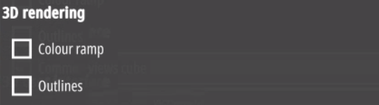
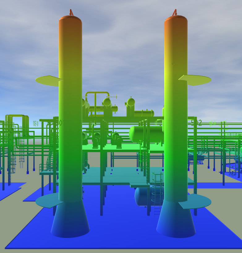
Color ramp creates a hight-map for the 3D model and colors objects accordingly.
Use old camera rotation behaviour changes the camera back to older UPV versions, rotating around the centre of the screen instead of an object.
Hide movement indicators hides the spheres showing the point the camera is rotating around while rotating.
Color Options

Here you can change the colors or patterns of the specified objects.
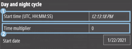
Day and Night Cycle
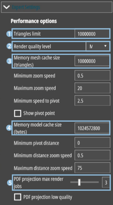
Expert Settings
Advanced users can adapt cache size, maximum number of triangles and maximum camera range to fit their needs.
|
|
Limits the maximum amount of triangles the system can load. |
|
|
Low: 30 FPS. Medium: 30 FPS, Ambient occlusion. High: 60 FPS, Ambinent occlusion, Shadows. |
|
|
Limits the model caching size by accessible triangles. |
|
|
Limits the model caching size by accessible bytes. |
|
|
This setting refers to the rendering of PDFs in the context of Zooming in and out. Limits the number of parallel rendering jobs/panels. |
About
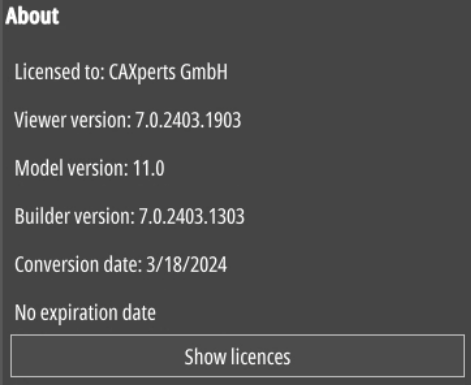
| Show licences: | This opens a new tab with legal information about software and licences used in UniversalPlantViewer. |
| Viewer version: | Shows the UniversalPlantViewer version you are using. |
| Model version: | Shows the version of the model you are using. |
| Builder version: | Shows the version of UniversalPlantViewer Builder the model was created with. |
| Conversion date: | Shows the conversion date of the model. |
| Expiration date: | Shows the date until you can use the current model. |
IntelliPID Settings
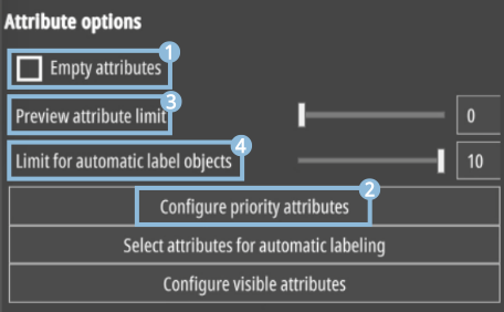
Attribute options
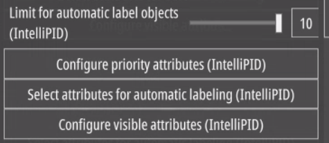
Automatic Labelling settings
Priority Attributes Settings
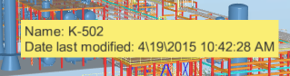
The priority attributes are always displayed first in the attributes panel. This does not affect custom attributes; they are always displayed directly after the attribute they are attached to by definition - see the section Custom Attributes in the chapter Custom settings . In case the item the mouse is hovering over lacks one of the priority attributes selected, the next available attribute will be displayed instead with accordingly raised priority.
General Information
| Colour settings | |
|---|---|
| Highlight | Changes the highlight colour of selected elements. |
| Selected elements | Changes the colour of selected elements. |
| Sheet background | Changes the P&ID background colour. |
| Background elements | Changes the colour of non-highlighted elements. |
| General settings | |
| Text offset | Changes the distance of the element-descriptions to the elements themselves. |
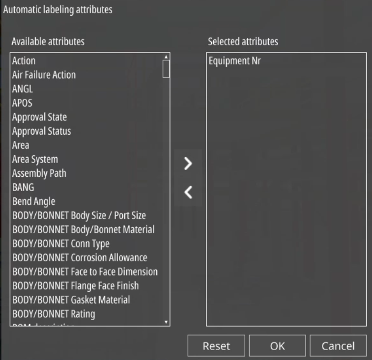
| Select attributes for automatic labelling | Opens a selection popup for choosing attributes for automatic labelling. To select an attribute, drag and drop it to the right list. See picture on the next page. |
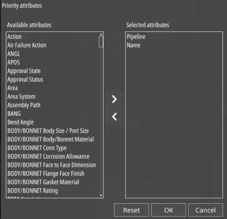
| Configure priority attributes | Opens a selection popup for choosing priority attributes. To select an attribute, drag and drop it to the right list. See picture on the next page. |
| Preview attribute limit | Defines the limit of the maximum number of attributes displayed in the tool tip that appears when hovering over any item. Attributes not available will be ignored. |
| Legend Font size | |
| Font size | Changes the font size used in the P&ID legend. |
| UI options | |
| UI scale | Changes the scale all User Interface (UI) elements are displayed by. |
| Reset UI scale | Resets the UI scale to normal (factor 1). |
| Attribute font size | Changes the font size, the attributes are displayed in the attributes panel on the right. |
GPS Instructions
To get things working properly, you’ll need to input calibration data
into the default configuration.
Use the template provided below, and
make sure to place it within the CommonSettings
section:
"CommonSettings": [
{
"GpsCalibration":{
"Latitude": 48.234706,
"Longitude": 11.679748,
"Altitude": 500.1,
"Bearing": 17,
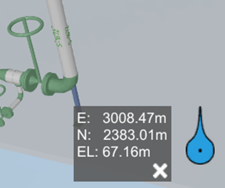
"ModelLocation": {
"x": 3005.50,
"y": 2385.32,
"z": 67.16
}
}
}
],
You must change the following values to match your plant:
- Latitude and Longitude refer to the real-world coordinates of a plant reference point. You can determine these using Google Earth by placing a Placemark at a known location.
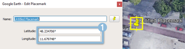
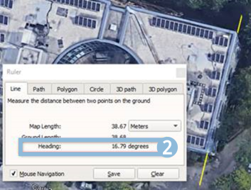
- Bearing indicates the deviation from true north for your plant. You can find this using Google Earth by using the measurement function to draw a line in the direction of ‘plant north’. The Heading value obtained can be used as the Bearing.
- The ModelLocation refers to the coordinates of your reference point’s model. Simply use these model coordinates for the ModelLocation.