Usage
When you run the software, the main window will show a dropdown list of available plants on your current Smart 3D site.

After selecting a plant from this list, please select a permission group that is allowed to place piping components.

SpecXpert will list the piping specifications of this plant:
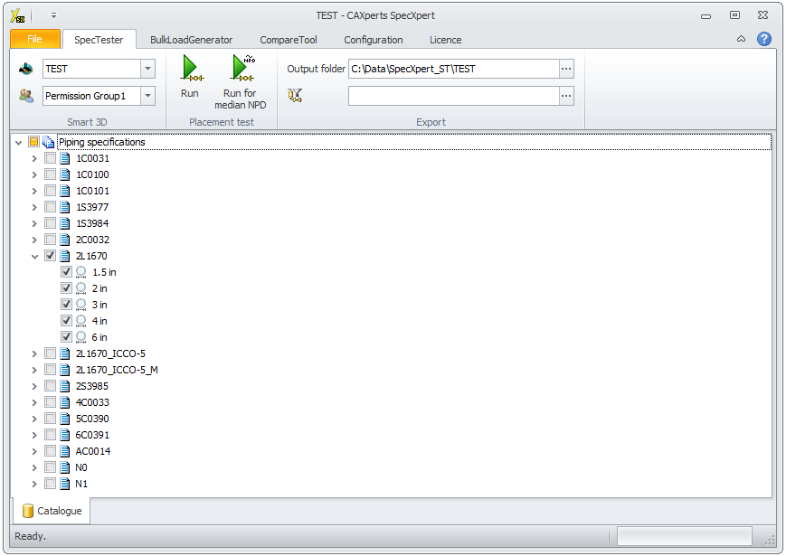
Test specifications
Check the checkboxes of the specifications (and nominal piping diameters) that you wish to test.
If you want to exclude certain parts from the test, add them to an
Excel exclusion list (sheet name: Excluded) and select the Excel file in
Additional Requirements ( ). Example files are included
in the templates folder of SpecXpert. Wildcards are currently not
possible (i.e. all columns have to be filled).
). Example files are included
in the templates folder of SpecXpert. Wildcards are currently not
possible (i.e. all columns have to be filled).
If the schedule thicknesses are calculated according to P/T
conditions using the ThicknessDataRule during the placement
(e.g. 1C0031, NPD26-NPD36, FirstSizeSchedule =ASME B31.3) it is possible
to define user defined values for P/T pairs. The pipeline name created
by SpecXpert contains the parameter of P/T. Add the pairs of P/T in
sheet UserDefined-DesignPTPipeRun and select the Excel file in
Additional Requirements ( ). Example files are included
in the templates folder of SpecXpert.
In the Output folder field you can enter manually, or use the "..." button to select, an output path and filename for the resultant report database.
Press the Run button to initiate the placement of the piping specification parts (if you use the Run for median NPD button, only the median NPD size of the selected specifications will be placed).
Please use Intergraph’s “Modify Site and Schema Location” tool to change the Smart 3D site.
For larger specifications, the placement process will typically take several hours. The placed components from the selected specification(s) will resemble the following:
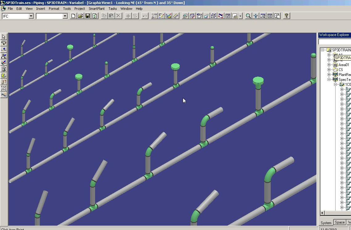
Each spec is placed in the "SpecXpert" piping system under a pipeline named after the specification.
Parts are placed on pipe runs according to their Nominal Piping Diameter. There is one main pipe run per NPD along with a separate pipe run per branch. The main pipe runs are vertically aligned from smallest to largest diameter.
Report output
The final outputs of SpecXpert are a Microsoft Excel (*.xlsx) file and a Microsoft Access database (*.mdb) file. These files contain several objects:
“StatusPlacedSpecParts” sheet / table
“ToDoList” sheet / table, presenting the erroneous parts.
“ExtractedPipingData” sheet / table
To-do list item interpretation
When the SpecXpert has finished placing the parts from the selected Specs, the next task is the interpretation of the to-do list items. These can either be found by looking at the SpecXpert Report database or by using the to-do list itself inside Smart 3D. The report database presents similar errors only once making it easier to see the actual number of spec issues.
While there are numerous rules in Smart specification writing that must be followed, this section will serve as a guideline for interpreting certain classes of errors that can abnormally occur when using SpecXpert.
Please refer to the Intergraph Smart 3D trouble shooting guide for in-depth listings of all possible to-do list items.
False positives
While every effort has been made to limit the number of 'false positive' to-do list entries reported by SpecXpert, it is possible that under certain conditions these false errors may occur.
One example of this case is with plug or end cap components where the end preparation of the connection port is not compatible with the pipe stock. This can arise when e.g. a plug was included for use with an instrument valve with a distinct end preparation.
While SpecXpert can save countless hours of repetitive work, the interpretation of the results still requires the understanding and domain-knowledge of a trained spec writer.
Duplicate to-do list items
For many errors, a to-do list item will be created for each of the parts involved. For instance, if a required flange size does not exist, a "No mating flange found" item will be created for both the pipe stock feature as well as the component feature. In these situations, fixing one issue will typically resolve multiple errors.
No part found
To-do list items that begin with "No Part Found in Catalog" indicate that the required part was not found in the catalogue.
This will often occur when SpecXpert attempts to place parts of a certain NPD on a pipe run whose pipe stock NPD is not included in the spec. For instance, SpecXpert places an olet part with a connection port of NPD 1.5 in. The specification only consists of stock from 2 inches upwards. The branch from the olet will indicate that "No Part Found in Catalog Data". This can be interpreted as either an error or a false positive if the part is understood to require a spec-break.
No <End Preparation> x <End Preparation> mating part found
This error indicates that the end preparation of the part is not compatible with the allowed end preparations of the pipe stock. The above "<End Preparation>" will be replaced with the name of the incompatible end preparation.
Export specifications
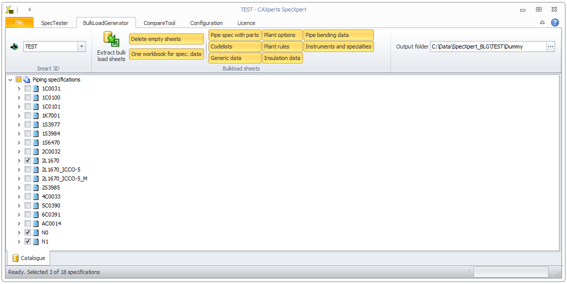
Check the specifications that you want to export on the treeview and selected which type of bulkload files to export from the BulkLoadGenerator tab, then press the Extract bulkload sheets button (to avoid empty sheets, select Delete empty sheets, to create only one workbook for more than one selected piping material classes, select One workbook for spec. data):
This process will typically take several minutes, the resulting bulkload sheets go to the folder specified in Output folder.
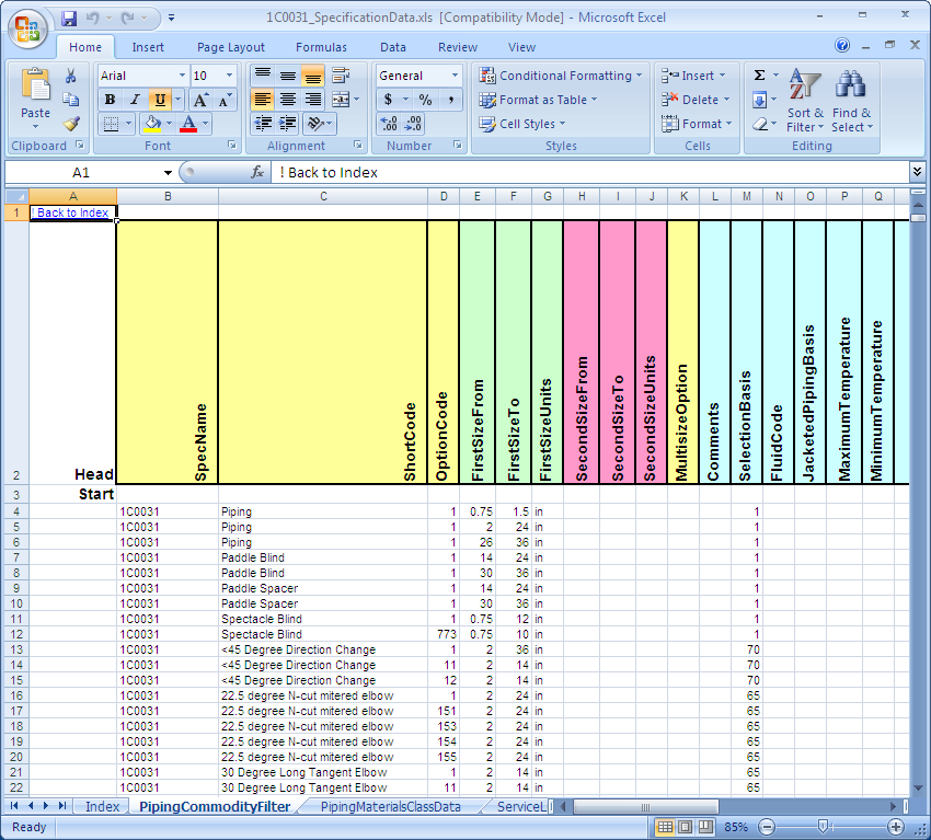
All options except the first option create Excel workbooks that are related to the option name. The first option Pipe spec with parts creates three types of workbooks:
Specification data. Excel workbook(s) for selected piping specification(s) with specification-dependent data sheets that include the attribute SpecName (e.g. “PipingCommodityFilter”, “ServiceLimits”, “NominalDiameters” etc.).
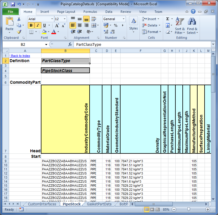
Piping catalog data. One Excel workbook for all selected piping specifications with their part data sheets (e.g. parts, valves, operators etc.).
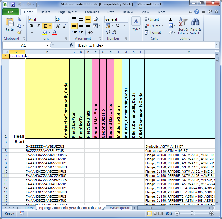
Material control data. One Excel workbook for all selected piping specifications with their part-dependent data (e.g. for pipes, valves, operators etc.).
Symbol icons. Symbol icons for all part classes. It doesn't exist any information about the symbol icon name or symbol icon folder in the Smart 3D catalogue database.
The symbol icon file listed in ...\SharedContentXYZ\SymbolIcon folder (.gif, .bmp or .jpg) is only used during the bulkload process.
The bulkload utility takes the symbol icon file according to the name and folder in the part class sheet and saves the graphic in a BLOB (binary large object) attribute on part level in the Smart 3D catalogue, but it isn't saved any information about the original name and folder on part or part class level in the Smart 3D catalogue database.
When SpecXpert has to export the symbol icon information it extracts the graphics out of the BLOB and saves it to a GIF file in a special directory named "BulkloadGenerator". The symbol icon name is created out of the part class name and the attribute PartDataBasis. To reuse the exported data copy the "BulkloadGenerator" directory (including all .gif files) to the ..\SharedContentXYZ\SymbolIcon folder assigned to the Smart 3D catalogue where you want to reuse the data.
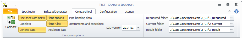
Compare specifications
SpecXpert enables the user to compare specifications against each other. Select the type of bulkload sheets to compare first (e.g. Codelists, Generic data, Plant rules etc.).
Ensure that the correct Smart 3D version is selected, then choose a folder with the requested files, a folder with the current files and the result folder and press Compare.
The exported file is formatted with the unit settings as defined in Configure units.
If bulkload files exist with PartClassType= PipeComponentClass, InstrumentClass or SpecialtyClass in the same folder then separate the files with different PartClassType into different folders before comparison.
Warning: All sheet names have to be unique for all files in the selected folder and have to appear in both folders to compare; otherwise they won’t get compared at all.
Units
Click on Configuration / Units to show the Configure units form to define the output format of units of measure for new bulkload files.
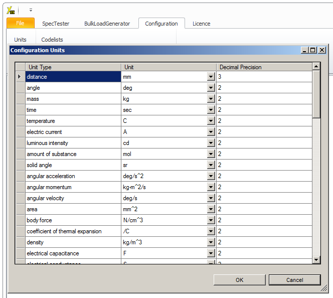
Unit Type: the quantity name of the unit.
Unit: the symbol of the unit (in Smart 3D notation).
Decimal Precision: the number of decimal places.
Codelists
Click on Configuration / Codelists to show the Configure Codelists to define the codelists which should be extracted.
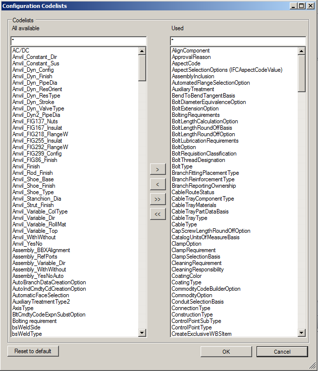
All codelists which should be extracted are listed on the right side. It is possible to move “available” or “used” codelists from one side to the other side with “>”, “<”, “>>” or “<<”. The default codelists are defined by the available codelists in the bulkload files of the Smart 3D installation.
Additional attribute PartNumber
The attribute PartNumber of PipeStockClass, PipeComponentClass or ClampClass may be extracted by selecting the option Extract attribute PartNumber additionally in the Configuration menu.
Status bar
The status bar shows information about the current state of the software (e.g. progress bars). If you double click on it, the log file opens: