Tutorial 2 - Simple custom instrument
Please read the tank tutorial first to learn and understand the basic functions of 3D SymbolDesigner, especially how to add, rename and edit nodes.
In this tutorial we will build a custom instrument part with two nozzles, a handwheel and insulation for the body part and the nozzles.
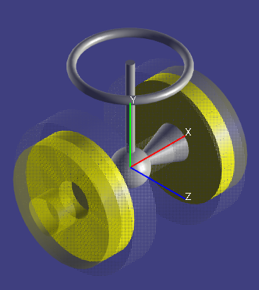
Piping symbols are using a right-handed coordinate system with y-axis up in SmartPlant 3D (there are exceptions from this rule: Three-way-valves with integral operator).
Create a new project
Click (
 )
to create a new symbol project.
)
to create a new symbol project.Change the coordinate system orientation by pressing the Y-Axis up button (
 ).
).
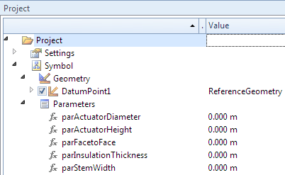
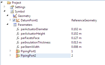
Add parameters
- Select the Parameters item in the menu tree. Then click five times
on the parameter button
(
 ).
).

- Rename the parameters: click on Parameter1 (press F2 if needed) and enter parFacetoFace. Repeat this for Parameter2 to Parameter5 with parActuatorHeight, parActuatorDiameter, parStemWidth and parInsulationThickness.
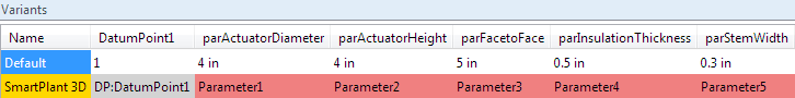
- The table of variants should now look like:
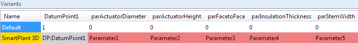
- Enter now the default values for the parameters into the table:
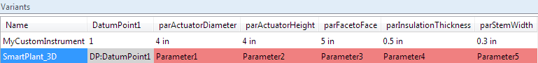
- Rename the variant Default to MyCustomInstrument:
- Rename the SmartPlant 3D parameter mappings: select the Parameter1 cell and click right mouse button. In the context menu select the Set SmartPlant 3D attribute. Choose the right attribute in the list box, check the Occurrence attribute and press the Apply button (add OA: in front of the parameter name, if the parameter is an occurrence attribute, i.e. an attribute which may be modified at runtime in SmartPlant 3D). Repeat this for Parameter2 to Parameter5. 3D SymbolDesigner checks the spelling. The parameters are now valid and the background colour turned to green:

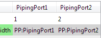
Add PipingPorts
- Expand the PipingPort parameter collection toolbar
icon (
 ) and click
the piping port (bolted preset). One PipingPort will be
added to the treeview and the list of variants. Repeat the step once
again to add a second one.
) and click
the piping port (bolted preset). One PipingPort will be
added to the treeview and the list of variants. Repeat the step once
again to add a second one.
|
|
Add nozzles
Click twice on the button for piping connectors (
 ). Press F2 to
rename the first nozzle node to VNoz1 and the second
one to VNoz2.
). Press F2 to
rename the first nozzle node to VNoz1 and the second
one to VNoz2.Rotate VNoz1 by 180 deg about the z axis.
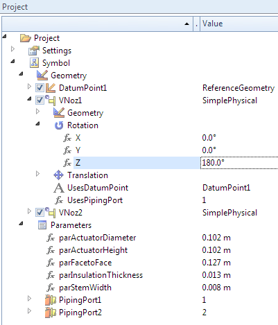
Move VNoz1 to the one end of the instrument by typing the following into its Translation.X subnode:
- parFacetoFace / 2 - PipingPort1.FlangeProjectionOrSocketOffset + PipingPort1.FlangeProjection + PipingPort1.SeatingOrGrooveOrSocketDepth.Move VNoz2 to the other end of the instrument by typing the following into its Translation.X subnode:
parFacetoFace / 2 + PipingPort2.FlangeProjectionOrSocketOffset - PipingPort2.FlangeProjection - PipingPort2.SeatingOrGrooveOrSocketDepth.
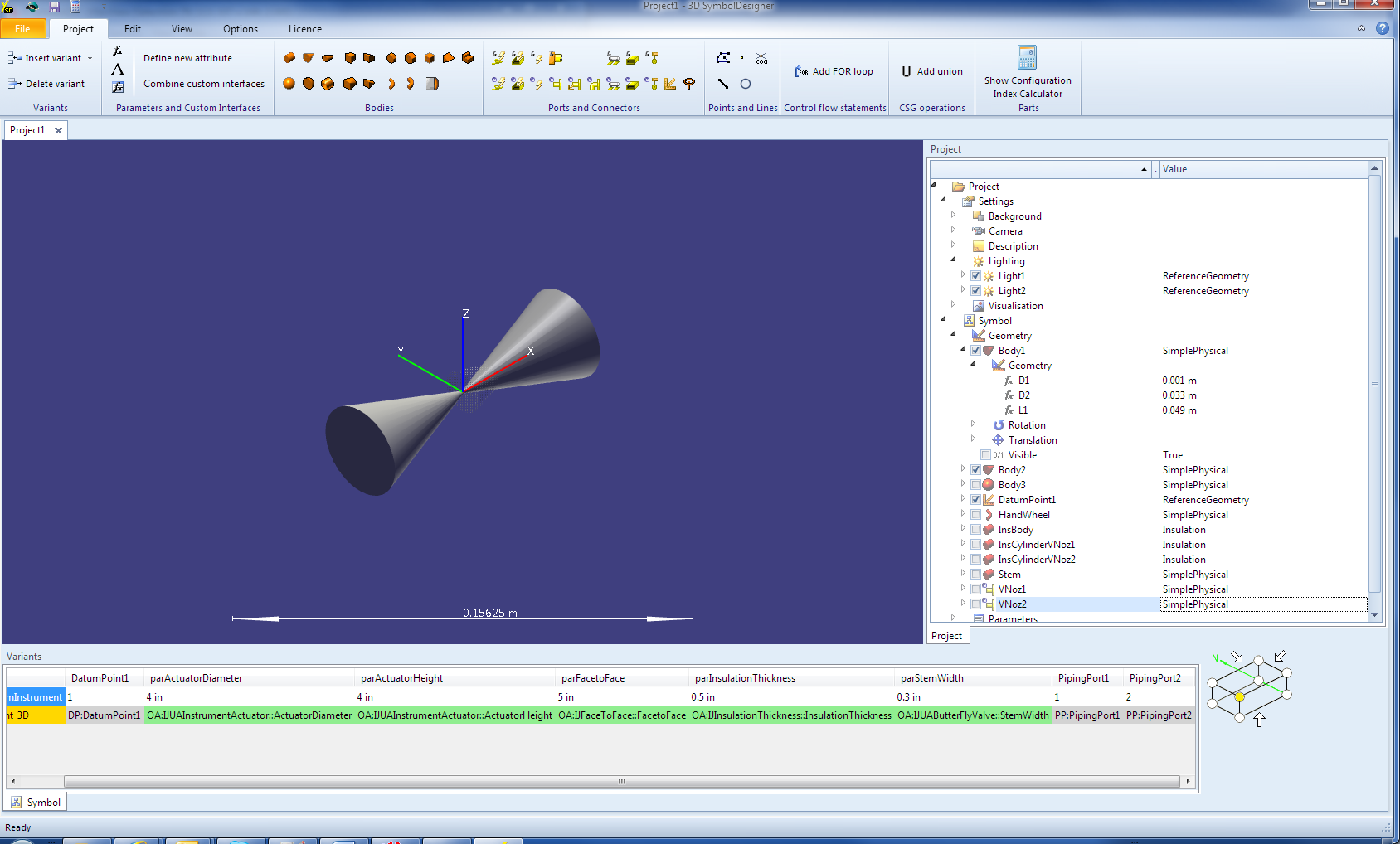
Add graphical primitives
Click twice on the cone button (
 ), once on sphere
(
), once on sphere
( ), once on torus
(
), once on torus
( ) and four times
on cylinder
(
) and four times
on cylinder
( ).
).
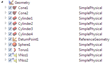
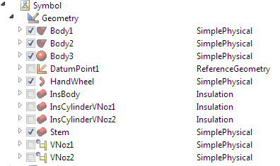
Rename Cone1 to Body1, Cone2 to Body2, Sphere1 to Body3, Torus1 to HandWheel, Cylinder1 to Stem, Cylinder2 to InsBody, Cylinder3 to InsCylinderVNoz1 and Cylinder4 to InsCylinderVNoz2.
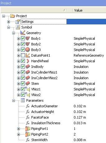
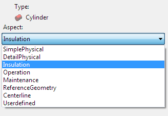
Right click on the InsBody node, select properties from the context menu and change the aspect from SimplePhysical to Insulation. Repeat this for InsCylinderVNoz1 and InsCylinderVNoz2.
Unselect all created primitives, except Body1 and Body2, using the checkbox in front of them.
Change to S/E isometric view as shown on the picture below.

Parameterise the primitives
Expand the Body1 node and the Geometry subnode and type in the following formula as value for the cone’s length (L1) property:
parFacetoFace / 2 - PipingPort1.FlangeOrHubThickness - PipingPort1.FlangeProjectionChange the value of the cone’s first diameter (D1) of the same node to 0.001. The value of a distance must not be zero, because SmartPlant 3D is not able to handle zero-distance values.
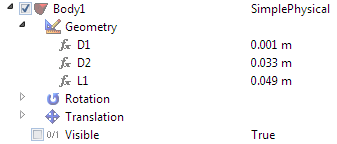
Type in the following as value for the D2 property: PipingPort1.PipingOutsideDiameter.
Expand the Body2 and underlying Geometry node and set the value of L1 to:
parFacetoFace / 2 - PipingPort2.FlangeOrHubThickness - PipingPort2.FlangeProjectionChange the value of D1 to 0.001.
Set the value of the cone’s second diameter (D2) to PipingPort2.PipingOutsideDiameter.
Rotate Body2 by typing 180 deg into its Rotation.Z property.
Use the zoom-in tool (
 ) until the two
cones fit to the view. Now it looks like this:
) until the two
cones fit to the view. Now it looks like this:
Expand the Body3 and the appropriate Geometry subnode to change the diameter value (D1) to the average outside diameter of the pipe by typing:
(PipingPort1.PipingOutsideDiameter + PipingPort2.PipingOutsideDiameter ) / 2.Change the L1 value of the Stem primitive to parActuatorHeight.
Set the Stem’s diameter (D1) to parStemWidth.
Rotate the Stem by assigning 90 deg to its Rotation.Z property.
Change the Value of the Handwheel’s D1 property to parStemWidth.
Type in the formula (parActuatorDiameter - parStemWidth) / 2 for the Handwheel’s radius (R1).
Set its angle (A1) property to 360 deg.
Expand the Handwheel’s Rotation subnode and set X to 90 deg.
Open the Translation branch and type in parActuatorHeight - parStemWidth / 2 for the Y value.
Set Z to -Geometry.HandWheel.Geometry.R1.
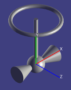
Switch on the checkboxes of Body3, Handwheel and Stem and zoom out until the instrument fits to the viewport.
Now you should see something like that:
Expand InsBody and its subnode Geometry to set its length L1 to:
Geometry.Body1.Geometry.L1 + Geometry.Body2.Geometry.L1Assign the formula Max(Geometry.Body1.Geometry.D1, Geometry.Body2.Geometry.D1) + 2 * parInsulationThickness to its D1 property.
Expand the Translation subnode and set X to -Geometry.Body1.Geometry.L1.
Change to the InsCylinderVNoz1 primitive and expand its subnode Geometry. Change the value of L1 to PipingPort1.FlangeOrHubThickness + parInsulationThickness.
Type the formula PipingPort1.FlangeOrHubOutsideDiameter + 2 * parInsulationThickness in D1.
Move this cylinder by changing its Translation.X property to -parFacetoFace / 2 + PipingPort1.FlangeProjection.
Expand the branch InsCylinderVNoz2 and the underlying Geometry node. Assign the formula PipingPort2.FlangeOrHubThickness + parInsulationThickness to the L1 value.
Set PipingPort2.FlangeOrHubOutsideDiameter + 2 * parInsulationThickness for the D1 property.
Move the cylinder by setting Geometry.Body2.Geometry.L1 - parInsulationThickness for X.
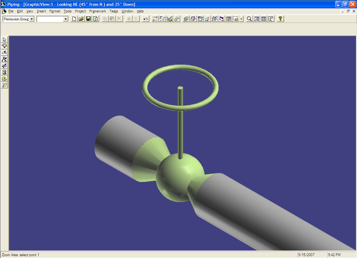
Tick all the remaining unchecked primitives. Now the viewport should look like this:
Export to SmartPlant 3D
The symbol is now ready to be exported to SmartPlant 3D. Save it first, and then click the (
) ) toolbar button
to export it.
) toolbar button
to export it.Optionally: Press the Reload Button. The catalogue structure will be loaded from the SP3D database. This will only work if a valid SP3D database server is available and configured (see item 52).
Add a new node below the Catalogue-Piping-Custom Instruments node, select it, give it a decent key and description and select it again.
On the second tab (Build) choose your target directory. You also may tick the checkbox Compile project below the Compiler settings topic. This will only work if the necessary SP3D libraries (dll) are registered and VisualBasic 6 is installed on this machine.
Click on the Start button. Before the export starts, the 3D SymbolDesigner checks if the parameters and the used variant names are valid (see Naming rules). This will avoid afterwards errors during the bulkload process. The occurred errors are shown in the Error list tab. By pressing an item of the list the cursor will move to the corresponding cell in the table.
Optionally: Export of a 3D PDF datasheet (see: Export of a 3D PDF datasheet).
Start the Bulkload tool and load the DLL. Usually the option Append to existing catalog must be selected for this purpose.
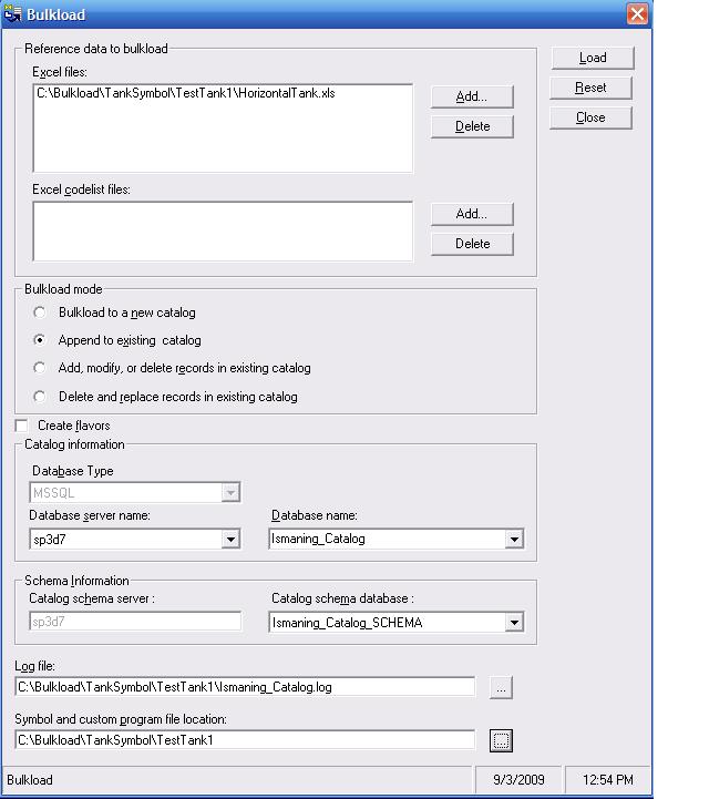
Check the log file for critical errors.
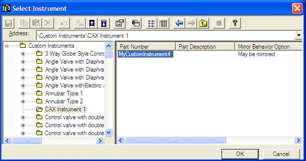
- Now you are able to use the symbol in SmartPlant 3D.