Objects
Select Objects
Select (multiple) objects by clicking on the checkbox next to them or on their name in the navigation bar (tree bar) at the top of the screen.

Common Attribute Display during Multi-Selection
To see common attributes for multiple objects, you can either hold down the Ctrl key while selecting or click on predefined groups or plant parts. This feature allows the simultaneous display of (custom) common attributes for up to 1000 objects.
Select Clipping Mode
|
|
“Select clipping mode” To improve object visibility, clip the view to exclude areas around selected objects. |
After deselecting the clipping mode it may take a few moments until the entire model is loaded again.
Please wait until the progress bar in the status bar stops changing.
Select from three clipping modes and customize them with
individual options:
Volume Clipping
|
|
“Volume clipping” Select an object and surround it with a rectangular clipping box that perfectly matches its size. This ensures that only fully enveloped objects will be visible. |
|
|
“Customise clipping” To modify the clipping box’s dimensions, slide the slider between 0 and 25 meters or drag a side of the box directly. For repositioning the box, simply drag the colored arrows. |
|
|
“Centre and fit selected objects” This option autofits the viewing perspective, if the volume of the clipped body is changed. |
|
|
“Save volume to clipboard” Save the volume of your current clipping to your clipboard to include it into an excel file. |
If you drag a side to a size smaller than 0 m, you will also move the opposite side of the box.
IntelliClipping
|
|
In “IntelliClipping”, the original clipping box conforms to the shape of the object itself, which is surrounded by the default selection box. |
- Use the slider to include all objects within the specified vicinity (0 to 25 meters) of the selected object in the clipping.
- Selecting None will display only the selected object.
Inverse Clipping
|
|
“Inverse clipping” gives a free view to the centre of the selected objects by clearing a quadrant along the x, y and z axis. All other quadrants will be displayed as usual. |
|
|
“Show/hide grid planes” You can add a grid that reacts to the camera’s distance to the object. The grid will have a size of 1 m x 1 m / 10 m x 10 m or 100 m x 100 m depending on the camera’s distance from the object. To change the size of the grid, drag the sides of the quadrant . |
|
|
“Save volume to clipping board” Save the volume of your current clipping to your clipboard to include it into an excel file. |
Example:
| min Y | min X | min Z | max Y | max X | max Z | |
|---|---|---|---|---|---|---|
| NewVolume | 3023.2Z | 2375.12 | 67.19 | 3037.21 | 2393.12 | 72.15 |
Centre and Fit
|
|
“Centre and fit selected objects” Select the objects you want to centre and fit to your window and click on this button. Without a selection, all elements will be fitted into the window. |
Toggle Visibility
|
|
“Toggle selcted objects visibility” To make objects vanish or reappear, simply select them and click on this button. |
Show Only
|
|
“Show only selected objects” This function vanishes every object except the selected ones. Toggle it to activate or deactivate it. |
Highlighting Objects
|
|
“Highlight selected objects” All objects except the selected ones will appear greyed out and semi-transparent. You can toggle the button to deactivate this function. |
Object Colours
Colourise Selected Objects
|
|
“Colourise selected objects” Change the display colour of selected objects by opening the colour menu. |
|---|
This menu is separated in four basic sections:
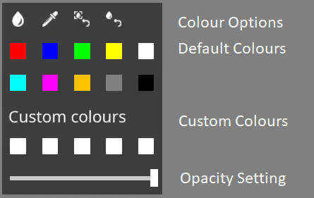
Colour Options
|
|
“Advanced colour selection” opens a pop-up menu for detailed colour selection, enabling you to pick from the full RGB spectrum of colours: |
|---|
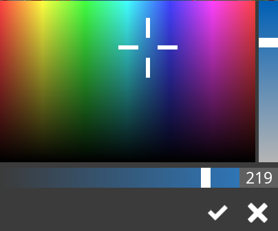
|
Once the colour is set up as required, confirm
[ The selected object(s) will instantly be displayed in the chosen colour. |
|
|
“Pick colours” lets you grab a colour from a 3D object
and save it in “custom colours”. Later, you can choose it from the
palette. Just activate the function, click an object to pick its color, and select a white custom color square to save it. |
|---|---|
|
|
“Clear style” resets the colour of the selected objects to their default colour, which was initially assigned during the building process. |
|
|
“Reset all colours” reverts all assigned colours for all objects to their default colour as initially assigned in the building process. |
Default Colours
The default colours section offers a basic set of predefined colours that can be applied to the currently selected objects.
Custom Colours
Custom colours are defined by the user using the colour picker function described earlier. Once defined, they can be used for colouring just like the default colours.
Opacity Setting
The slider at the bottom adjusts opacity, with the leftmost position being fully transparent and the rightmost position indicating that the selected objects are fully opaque.
Creating a Colour File
|
|
Your model is loaded with a default color file. But you can also create a “Custom color file” and load it via the file management menu. |
Custom color files can be created using Excel by inputting a color and a corresponding condition. You can use color names or HTML color codes starting with “#” followed by six digits representing the intensity of red, green, and blue, along with two optional digits for opacity.
For condition, you can enter attributes like task,
piping, name, system path, or any other relevant attribute.
Aspect is an optional value used to color
insulation and/or simple physical for piping.
Example:
| Color | Condition |
|---|---|
| red | Task=Equipment |
| blue | Task=Structure |
| #FF00FF22 | Task=Supports |
| red | Task=Cableway |
| red | Task=Conduit |
| red | Task=HVAC |
| #FF00FF | piping |
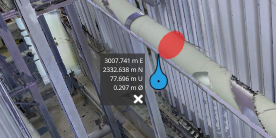
Measure Distances
|
|
“Measure distances” creates markers that are placable on outlines and corners of 3D objects. The markers can be moved by dragging them. |
|
|
“Create new distance measurement” creates two connected markers and shows the distance between them, as well as distances in the XYZ planes. |
|
|
“Create new coordinate measurement” generates a single measurement marker attached to its coordinate information. |
|
|
“Prevent East-Axis/North-Axis/Up-Axis movement” |
|
|
“Ignore intelligent targetting” is explained in more detail with example images below. |
|
|
This button “Estimates the diameter” of cylindrical objects, e.g. pipes. This feature is especially useful for laser scans, it also displays a red diameter to provide visual assistance. |
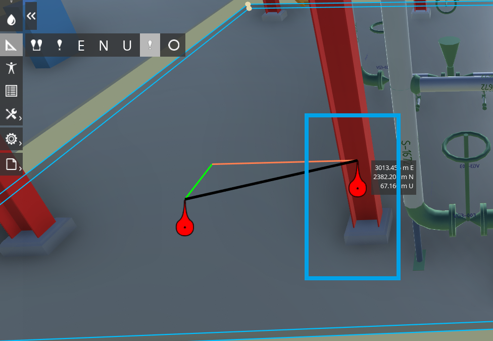
Intelligent Targetting
| Activated intelligent targetting | Deactivated intelligent targetting |
|---|---|
|
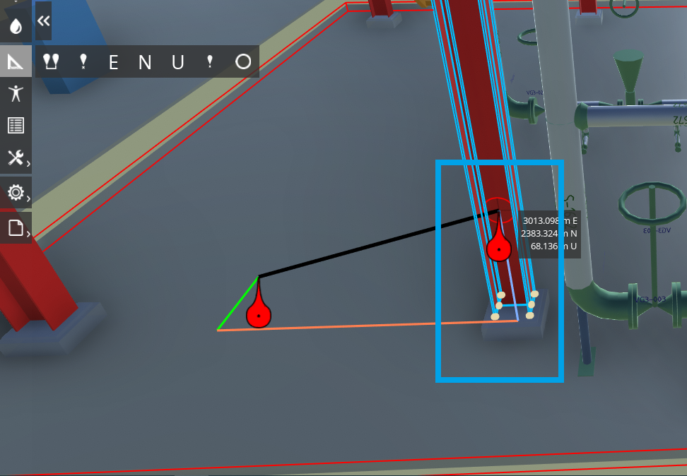
|
- With intelligent targeting activated, the marker only selects positions on the previously selected object. For instance, in the image above, the right marker (highlighted in blue) can be positioned on a spot behind the red vertical beam.
- When intelligent targeting is deactivated, the right marker (highlighted in blue) now selects a position on any object it hovers over. The perspective of the operator is a key factor in this procedure.
Tolerance “100” Enable “Advanced Graphics Handling for measuring and line tracking”.