Usages
File
New
New
(![]() ) creates a new
3D SymbolDesigner symbol project.
) creates a new
3D SymbolDesigner symbol project.
Open
Open
(![]() ) shows a file
open dialogue. 3D SymbolDesigner supports 3D
SymbolDesigner project files (.xlsx and .xls, Microsoft Excel
files with symbol geometry data and variants; .xml 3D SymbolDesigner XML
symbol geometry data).
) shows a file
open dialogue. 3D SymbolDesigner supports 3D
SymbolDesigner project files (.xlsx and .xls, Microsoft Excel
files with symbol geometry data and variants; .xml 3D SymbolDesigner XML
symbol geometry data).
Save
Save
(![]() ) stores the
content of the active form. If the file name is unknown, a Save
As dialogue is shown.
) stores the
content of the active form. If the file name is unknown, a Save
As dialogue is shown.
Save as
Save as opens a Save As dialogue where the filename to save the content of the active form to can be chosen.
Export to SmartPlant 3D
Export to SmartPlant 3D
(![]() ) shows a
configuration dialogue (SmartPlant 3D Wizard) for the export to
Intergraph SmartPlant 3D.
) shows a
configuration dialogue (SmartPlant 3D Wizard) for the export to
Intergraph SmartPlant 3D.
The dialogue shows two tabs for configuring the export to SmartPlant 3D.
Under ideal conditions, the Wizard will produce a Visual Basic project containing the symbol geometry, compile it, register the DLL, produce an Excel file for the catalogue bulk load and start the bulk load to the catalogue.
The Symbol tab provides a catalogue tree to select the target position in the SmartPlant 3D catalogue.
| Discipline | Bulkload sheet | |
|---|---|---|
| Equipment | Add/select a folder below Equipment. Add/select a node below this folder. |
|
| Equipment component | Add/select a folder below Equipment Components. Add/select a node below this folder. |
|
| Piping spec symbol/standard instrument/standard specialty | Select Piping | - |
| Piping custom instrument (on-the-fly) | Add/select a node below Piping-Custom Instruments. |
|
| Piping custom specialty (on-the-fly) | Add/select a node below Piping-Custom Specialties. |
|
| Hangers and supports | Select Supports | - |
| HVAC component | Add/select a folder below Duct Add/select a node below this folder. |
|
When the Piping or Supports node is selected, 3D SymbolDesigner will produce a Visual Basic project/DLL for a piping symbol (but no Excel bulk load file).
A file called ComponentTree.xml is parsed in for this dialogue, which is generated by the Reload button and may be modified manually to represent the catalogue tree of the target system. - The third column shows the PartClassType of the symbol. If none is selected, 3D SymbolDesigner will assume that the type is PipeComponentClass.
The checkbox Write full hierarchy allows the user in the case of a re-export to export the full R-Hierarchy in the bulkload file. Otherwise a re-export produces an empty R-Hierarchy sheet.
The Build tab shows the project settings from the project tree view and allows the configuration of the Visual Basic code output and compilation.
Error logging: the log file goes here.
Project target folder: the Visual Basic code goes here.
Output format: VB6 code or VB.NET.
Make DLL binary compatible: Recommended to be switched on, when the Visual Basic code is not manually modified by the user.
Include advanced debugging code: Recommended to be switched off, produces debugging code in the Visual Basic project that may slow down your system.
Compile project: works only when Visual Basic 6.0 is installed and all Intergraph DLLs that are usually needed for SmartPlant 3D symbol development are available on the system. Starts Visual Basic and compiles the Visual Basic project.
To compile the Visual Basic 6 code the SmartPlant 3D ‘Programming Resources’ have to be installed.
- Delete Visual Basic files after compiler run: cleans up the target directory.
The Start button executes the workflow defined on the Symbol and Build tabs. Before the export starts, the 3D SymbolDesigner checks if the parameters and the used variant names are valid (see 0 Naming rules). This will avoid errors during the bulkload process afterwards. Any errors will be shown on the Error list tab. Click on an item of the list to move the cursor to the corresponding cell of the table.
Export of a 3D PDF datasheet
For the 3D PDF datasheet export a PlantDocumentDesigner template file is necessary (Template.pdprj). A sample file is provided in the Samples\3D PDF\Template subdirectory of the 3D SymbolDesigner installation folder. You can either edit the template file with an xml editor or much more comfortably (WYSIWYG) with the CAXperts PlantDocumentDesigner. To activate the 3D PDF export the path to the Template.pdprj file has to be specified on the Options tab of 3DSymbolDesigner:
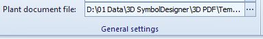
If there is no path chosen or the path is incorrect no 3D PDF export will occur. Otherwise a 3D PDF datasheet will be created in the same process whenever the Export to SmartPlant 3D occurs. Therefore you have to press the Start button of the Export to SmartPlant 3D configuration dialogue (SmartPlant 3D Wizard) to start the export. To deactivate the 3D PDF export you can double click on the Plant document file text on the Options tab or you can delete the template file under the chosen path.
Optionally: it is possible to add a company logo (.jpg) and a drawing (.jpg) to the 3D PDF datasheet and to fill the text items on the datasheet with values from an ini-file.
- Company logo
Define the path to your company logo (.jpg) in the Template.pdprj file by using an xml editor. Furthermore you can use the PlantDocumentDesigner to add your company logo to the Template.pdprj.
- Drawing
To add a drawing (.jpg) file to the 3D PDF datasheet you must save your drawing in the project target folder that you have defined on the Build tab of the Export to SmartPlant 3D configuration dialogue (SmartPlant 3D Wizard). If the drawing file has the same name as the class name defined on the Symbol tab in the tree under the key column then the drawing will be added to the 3D PDF file. Otherwise, if there is no file with the same name as the class, 3D SymbolDesigner will create a screenshot, save it in the target folder, and add it to the 3D PDF file.
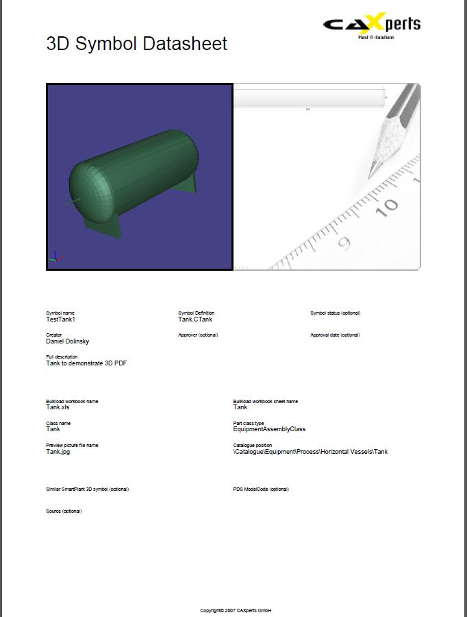
- Ini file
To fill out optional fields and overwrite fields on the first page of the 3D PDF file you can define some input values in an ini file. An ini example file is provided in the Samples\3D PDF\Ini subdirectory of your 3D SymbolDesigner installation. You must save your ini file in the project target folder that you have defined on the Build tab of the Export to SmartPlant 3D configuration dialogue (SmartPlant 3D Wizard). If it has the same name as the class name defined on the Symbol tab in the tree under the key column then the input of the ini- file will be added to the 3D PDF file.
To define values in the ini file use this syntax:
###FullDescription###=Full description of the symbol
In the 3D PDF will appear “Full description of the symbol” in the “FullDescription” item (defined by setting its text to ###FullDescription### in the xml file). If there is no assignment in the ini- file the item will be empty or filled with automatic values by 3D SymbolDesigner.
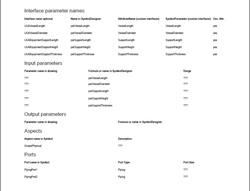
On the second page of the 3D PDF file interface parameter names, input parameters, output parameters, aspects and ports get listed. The items with “???” could not be filled by 3D SymbolDesigner for some reason and can be edited (e.g. using Adobe Acrobat) manually.
Distributing symbols
If the symbol being distributed is an existing symbol that has been modified, the major version number in the Visual Basic project properties must be increased by 1. Increasing the major version number by 1 forces the recomputation of existing symbol occurrences when the Synchronize Model With Catalog command in Project Management is run. If an existing symbol is modified and distributed, all the new symbol occurrences will use the new symbol (unless the new occurrence uses an existing entry of symbol's cache). If an existing symbol is modified and distributed, and an existing occurrence is recomputed, it will use the new symbol if the recomputation results in creation of a new entry in the symbol's cache.
Preferred method
- Place the dll for the new or modified symbol on the server's symbols share and public the symbol with the Update Custom Symbol Configuration command in Project Management.
Non preferred method
On a client machine, copy the dll from the server to the local [Product Directory]\CatalogData\Symbols\bin folder.
Register the new .dll by clicking Start > Run and typing: regsvr32 "[Product Directory]\CatalogData\Symbols\bin\<name of dll>".
Repeat steps 2 and 3 on each client machine.
Recent documents
The most recently used files are listed here.
About CAXperts 3D SymbolDesigner
About shows a dialogue with information about the software product and version, the System Info button starts Microsoft System Information which provides useful additional information about the hardware and software configuration of the computer system.
Exit
Exit ends CAXperts 3D SymbolDesigner.
Project
Variants
A variant is a named group of parameter values which can be used for testing the parameterisation of a symbol. Variants are exported to SmartPlant 3D bulk load sheets.
Insert variant
Insert variant ( ) inserts
a variant in the symbol project.
) inserts
a variant in the symbol project.
Delete variant
Delete variant ( ) deletes the selected
variant from the symbol project.
) deletes the selected
variant from the symbol project.
Parameters
Add parameter
A parameter ( ) is an
element of the symbol tree which consists of a name and a value. The
name is unique in the whole symbol project and can be referenced by any
formula. A parameter is mapped to a SmartPlant 3D parameter name by the
SmartPlant 3D mapping row in the variants grid of the symbol project. If
a lookup in Config.xls in the data subdirectory of 3D SymbolDesigner
shows that this parameter name is there, the parameter mapping will get
a green background; else it will stay red which means that this
parameter will not be exported to SmartPlant 3D. The user can also
change the mapping using the context menu (right click).
) is an
element of the symbol tree which consists of a name and a value. The
name is unique in the whole symbol project and can be referenced by any
formula. A parameter is mapped to a SmartPlant 3D parameter name by the
SmartPlant 3D mapping row in the variants grid of the symbol project. If
a lookup in Config.xls in the data subdirectory of 3D SymbolDesigner
shows that this parameter name is there, the parameter mapping will get
a green background; else it will stay red which means that this
parameter will not be exported to SmartPlant 3D. The user can also
change the mapping using the context menu (right click).
Add text parameter
A text parameter ( ) is an element of
the symbol tree which consists of a name and a text value. The name is
unique in the whole symbol project and can be referenced by any formula.
A text parameter is mapped to a SmartPlant 3D parameter name by the
SmartPlant 3D mapping row in the variants grid of the symbol project.
Text parameters may contain non-numeric values.
) is an element of
the symbol tree which consists of a name and a text value. The name is
unique in the whole symbol project and can be referenced by any formula.
A text parameter is mapped to a SmartPlant 3D parameter name by the
SmartPlant 3D mapping row in the variants grid of the symbol project.
Text parameters may contain non-numeric values.
Bodies
3D SymbolDesigner contains the full set of shapes known from Intergraph PDS.
These are the rules as to how geometric transformations to a shape are applied:
The shape is placed at the origin of the world coordinate system (i.e. the locale coordinate system of the shape matches the world coordinate system (marked red-green-blue).
The shape’s geometry is scaled according to the values set in its .Geometry sub-tree.
The shape is rotated about the global X axis by the angle specified in its .Rotation.X item.
The shape is rotated about the global Y axis by the angle specified in its .Rotation.Y item.
The shape is rotated about the global Z axis by the angle specified in its .Rotation.Z item.
The shape is translated by the distances specified in its .Translation subtree.
Shapes already included with 3D SymbolDesigner are described below (the anchor of the shape is marked magenta-yellow-cyan).
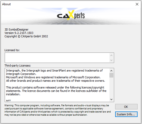
Cylinder
| 3D SymbolDesigner | PDS | Comment |
|---|---|---|
| Cylinder. | Right Circular Cylinder (1) | |
| .Translation.X | X | |
| .Translation.Y | Y | |
| .Translation.Z | EL | |
| .Geometry.L1 | A | |
| .Geometry.D1 | B |
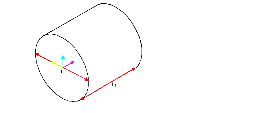
Cone
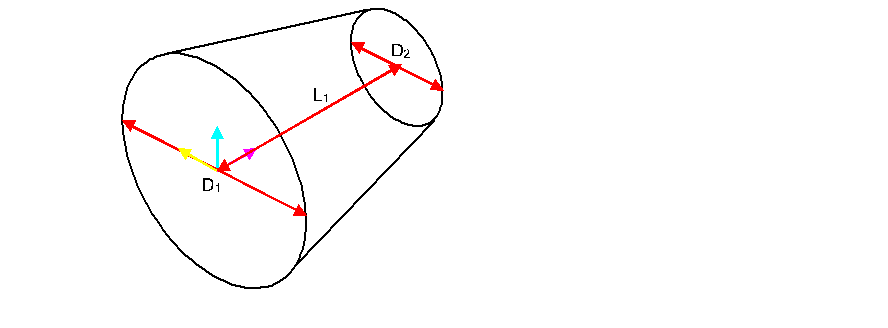
| 3D SymbolDesigner | PDS | Comment |
|---|---|---|
| Cone. | Right Circular Cone (2) | |
| .Translation.X | X | |
| .Translation.Y | Y | |
| .Translation.Z | EL | |
| .Geometry.L1 | A | |
| .Geometry.D1 | B | |
| .Geometry.D2 | C |
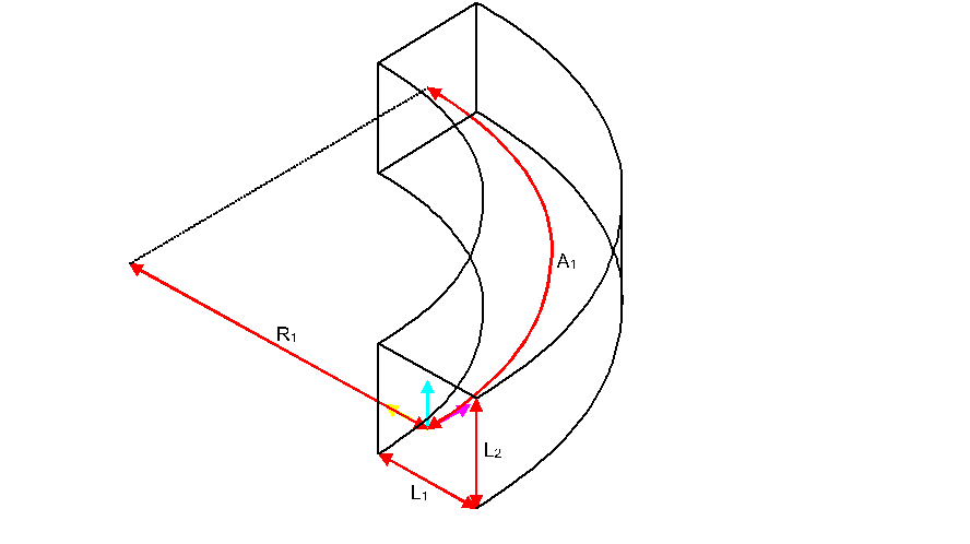
Eccentric circular cone
| 3D SymbolDesigner | PDS | Comment |
|---|---|---|
| EccentricCircularCone. | Eccentric Circular Cone (3) | |
| .Translation.X | X | |
| .Translation.Y | Y | |
| .Translation.Z | EL | |
| .Geometry.A1 | Angle of the left face | |
| .Geometry.A2 | Angle of the right face | |
| .Geometry.AR1 | Aspect ratio of the left face | |
| .Geometry.AR2 | Aspect ratio of the right face | |
| .Geometry.D1 | B | |
| .Geometry.D2 | C | |
| .Geometry.L1 | A | |
| .Geometry.L2 | Horizontal offset of the right face | |
| .Geometry.L3 | Vertical offset of the right face |
Truncated rectangular prism
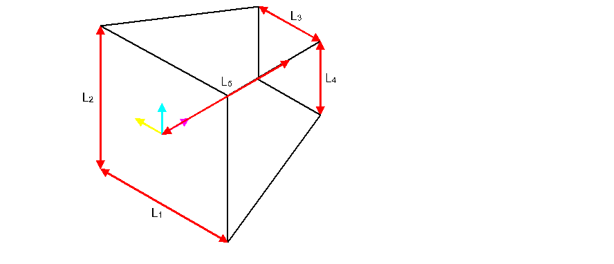
| 3D SymbolDesigner | PDS | Comment |
|---|---|---|
| TruncatedRectangularPrism. | Truncated Rectangular Prism (12) | |
| .Translation.X | X | |
| .Translation.Y | Y | |
| .Translation.Z | EL | |
| .Geometry.L1 | A | |
| .Geometry.L2 | B | |
| .Geometry.L3 | C | |
| .Geometry.L4 | D | |
| .Geometry.L5 | E |
Eccentric rectangular prism
| 3D SymbolDesigner | PDS | Comment |
|---|---|---|
| EccentricRectangularPrism. | Eccentric Rectangular Prism (13) | |
| .Translation.X | X | |
| .Translation.Y | Y | |
| .Translation.Z | EL | |
| .Geometry.A1 | Angle of the left face | |
| .Geometry.A2 | Angle of the right face | |
| .Geometry.L1 | A | |
| .Geometry.L2 | B | |
| .Geometry.L3 | C | |
| .Geometry.L4 | D | |
| .Geometry.L5 | E |
Octagonal solid
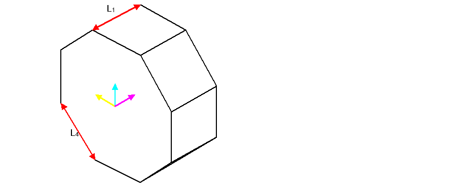
| 3D SymbolDesigner | PDS | Comment |
|---|---|---|
| OctagonalSolid. | Octagonal Solid (8) | |
| .Translation.X | X | |
| .Translation.Y | Y | |
| .Translation.Z | EL | |
| .Geometry.L1 | A | |
| .Geometry.L2 | B | Ignored |
| .Geometry.L3 | C | |
| .Geometry.L4 | D |
Hexagonal solid
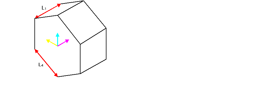
| 3D SymbolDesigner | PDS | Comment |
|---|---|---|
| HexagonalSolid. | Hexagonal Solid (7) | |
| .Translation.X | X | |
| .Translation.Y | Y | |
| .Translation.Z | EL | |
| .Geometry.L1 | A | |
| .Geometry.L2 | B | Ignored |
| .Geometry.L3 | C | |
| .Geometry.L4 | D |
Box
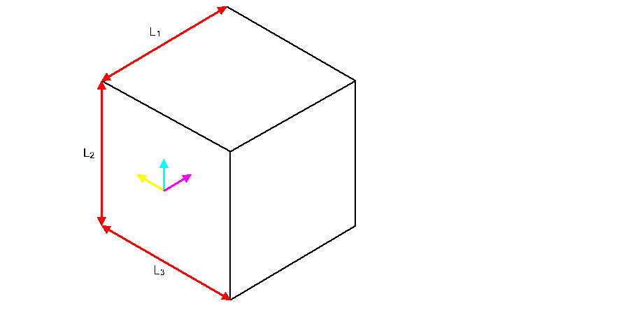
| 3D SymbolDesigner | PDS | Comment |
|---|---|---|
| Box. | Rectangular Solid (6) | |
| .Translation.X | X | |
| .Translation.Y | Y | |
| .Translation.Z | EL | |
| .Geometry.L1 | A | |
| .Geometry.L2 | B | |
| .Geometry.L3 | C |
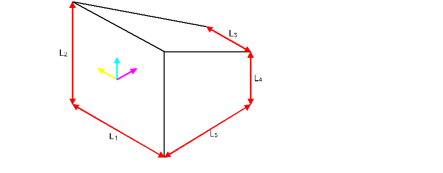
Triangular solid
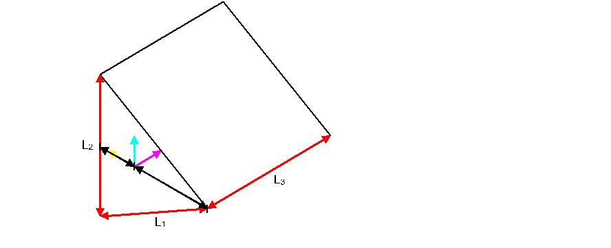
| 3D SymbolDesigner | PDS | Comment |
|---|---|---|
| TriangularSolid. | Triangular Solid (5) | |
| .Translation.X | X | |
| .Translation.Y | Y | |
| .Translation.Z | EL | |
| .Geometry.L1 | A | |
| .Geometry.L2 | B | |
| .Geometry.L3 | C | |
| .Geometry.A1 | D | Ignored |
Extruded solid
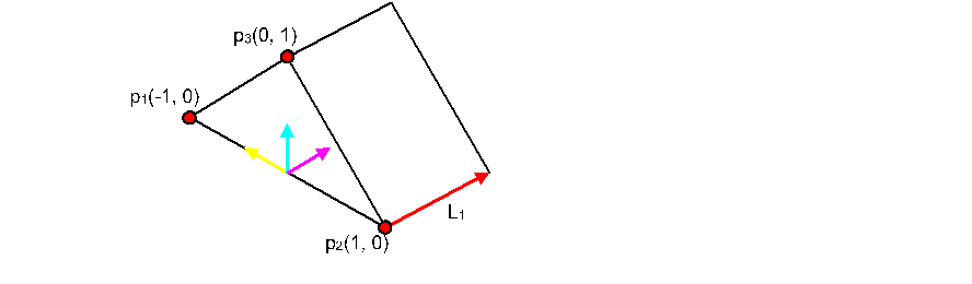
Additional UV points can be added by Insert → Vertices → UV point
| 3D SymbolDesigner | PDS | Comment |
|---|---|---|
| ExtrudedSolid. | User Projected Shape (9) | |
| .Translation.X | X | |
| .Translation.Y | Y | |
| .Translation.Z | EL | |
| .Geometry.L1 | Projection | |
| .Geometry.Vertices.UVVector1.U | 1 X | |
| .Geometry.Vertices.UVVector1.V | 1 Y | |
| … | … | |
| .Geometry.Vertices.UVVector20.U | 20 X | |
| .Geometry.Vertices.UVVector20.V | 20 Y |
Sphere
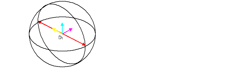
| 3D SymbolDesigner | PDS | Comment |
|---|---|---|
| Sphere. | Sphere (17) | |
| .Translation.X | X | |
| .Translation.Y | Y | |
| .Translation.Z | EL | |
| .Geometry.D1 | A |
Semisphere
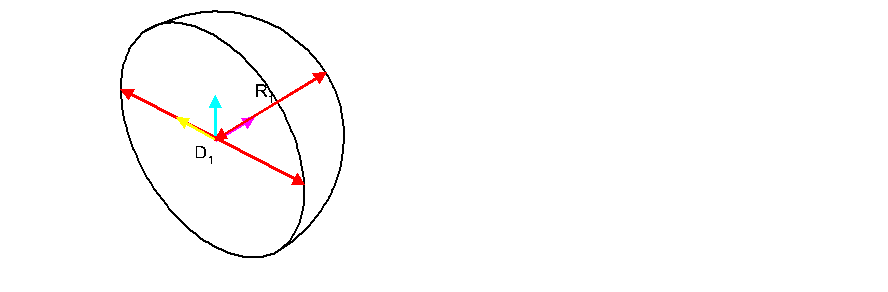
| 3D SymbolDesigner | PDS | Comment |
|---|---|---|
| Semisphere. | Semi-Elliptical Head (4) | |
| .Translation.X | X | |
| .Translation.Y | Y | |
| .Translation.Z | EL | |
| .Geometry.D1 | A | |
| .Geometry.R1 | B |
Rotational solid
See extruded solid. There is no similar object in PDS.
Transition element
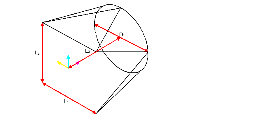
| 3D SymbolDesigner | PDS | Comment |
|---|---|---|
| TransitionElement. | Transition Element (15) | |
| .Translation.X | X | |
| .Translation.Y | Y | |
| .Translation.Z | EL | |
| .Geometry.L1 | A | |
| .Geometry.L2 | B | |
| .Geometry.L3 | C | |
| .Geometry.D1 | D |
Eccentric transition element
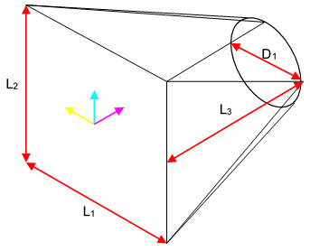
| 3D SymbolDesigner | PDS | Comment |
|---|---|---|
| EccentricTransitionElement. | Eccentric Transition Element (16) | |
| .Translation.X | X | |
| .Translation.Y | Y | |
| .Translation.Z | EL | |
| .Geometry.A1 | Angle of the left face | |
| .Geometry.A2 | Angle of the right face | |
| .Geometry.L1 | A | |
| .Geometry.L2 | B | |
| .Geometry.L3 | C | |
| .Geometry.L4 | 1st offset of the right face | |
| .Geometry.L5 | 2nd offset of the right face | |
| .Geometry.D1 | D |
Torus
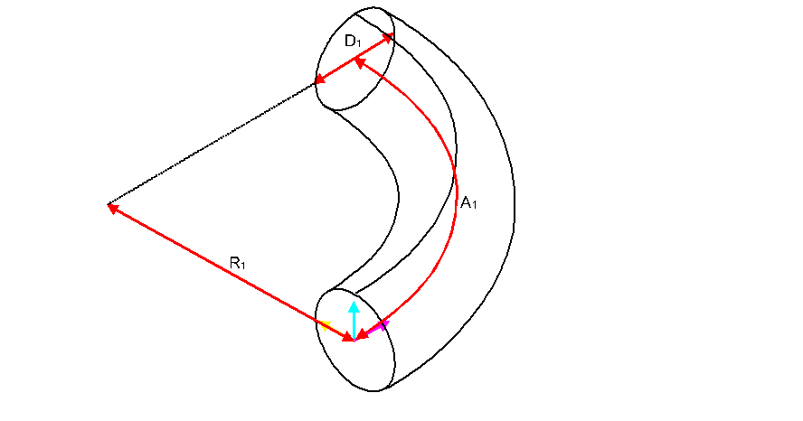
| 3D SymbolDesigner | PDS | Comment |
|---|---|---|
| Torus. | Circular Torus (10) | |
| .Translation.X | X | |
| .Translation.Y | Y | |
| .Translation.Z | EL | |
| .Geometry.D1 | A | |
| .Geometry.R1 | B | |
| .Geometry.A1 | C |
Rectangular torus
| 3D SymbolDesigner | PDS | Comment |
|---|---|---|
| RectangularTorus. | Rectangular Torus (11) | |
| .Translation.X | X | |
| .Translation.Y | Y | |
| .Translation.Z | EL | |
| .Geometry.L1 | A | |
| .Geometry.L2 | B | |
| .Geometry.R1 | C | |
| .Geometry.A1 | D |
Vessel end
| 3D SymbolDesigner | PDS | Comment |
|---|---|---|
| .Geometry.D1 | - | |
| .Geometry.L1 | - | |
| .Geometry.EndType | - | DIN28011 or DIN28013 |
Ports & connectors
A parameter collection ( ,
,  ,
,  ,
,  ,
,  ,
,  ,
,  ) contains
parameters which are usually provided by SmartPlant 3D for the placement
and dimensioning of nozzles. The user can set values in this collection
for testing purposes. The values are not exported, they will be provided
at runtime by SmartPlant 3D. Each connector needs a parameter collection
of its own. Parameter collections get mappings with grey background
colour.
) contains
parameters which are usually provided by SmartPlant 3D for the placement
and dimensioning of nozzles. The user can set values in this collection
for testing purposes. The values are not exported, they will be provided
at runtime by SmartPlant 3D. Each connector needs a parameter collection
of its own. Parameter collections get mappings with grey background
colour.
Cable connector
A Cable connector ( )
symbolises the start position and direction of cables leading away from
the symbol.
)
symbolises the start position and direction of cables leading away from
the symbol.
Cable tray connector
A Cable tray connector () symbolises the start position, direction
and orientation of cable trays leading away from the symbol.
Conduit connector
A Conduit connector ( )
symbolises the start position and direction of conduits leading away
from the symbol.
)
symbolises the start position and direction of conduits leading away
from the symbol.
Piping connector
A Piping connector ( ,
formerly Variable nozzle) symbolises the start position
and direction of pipes leading away from the symbol.
,
formerly Variable nozzle) symbolises the start position
and direction of pipes leading away from the symbol.
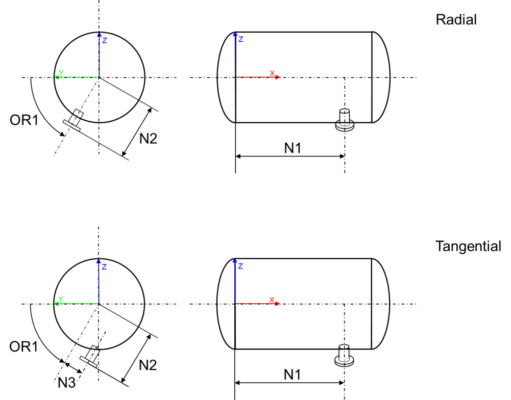
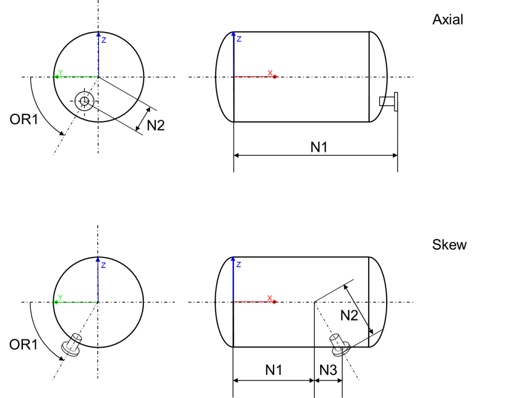
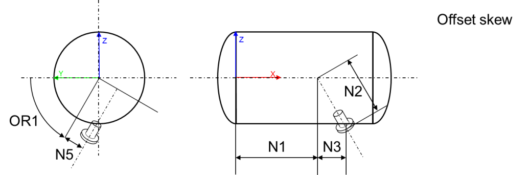
Smart piping connector for datum point based nozzles on equipment
Smart piping connectors ( )
use N1, N2, N3, N5 and OR1 to specify their position in relation to a
datum point. Therefore they can only be used within the Geometry subnode
of a DatumPoint object and will work on equipment
symbols only. The following PlacementType values are allowed:
)
use N1, N2, N3, N5 and OR1 to specify their position in relation to a
datum point. Therefore they can only be used within the Geometry subnode
of a DatumPoint object and will work on equipment
symbols only. The following PlacementType values are allowed:
Radial
Tangential
Axial
Skew
OffsetSkew
Elbow piping connector
An Elbow piping connector ( ) symbolises the start position and
direction of pipes leading away from the symbol.
) symbolises the start position and
direction of pipes leading away from the symbol.
Foundation connector
A Foundation connector ( ) symbolises the start position and
direction of foundation connections.
) symbolises the start position and
direction of foundation connections.
HVAC connector
A HVAC connector ( )
symbolises the start position and direction of HVAC pipes leading away
from the symbol.
)
symbolises the start position and direction of HVAC pipes leading away
from the symbol.
On the port, the following codelist numbers are available for the CrossSectionShape: 1 Rectangular, 3 Flat Oval, 4 Round.
Hanger connector
A Hanger connector ( )
symbolises the start position and direction of support/hanger
connections.
)
symbolises the start position and direction of support/hanger
connections.
Datum Point
A plain project has already one datum point ( ). To add additional ones, please use this button.
Nozzles get always logically attached to DatumPoint1 as long as they
don’t belong to the Geometry subnode of another datum point.
). To add additional ones, please use this button.
Nozzles get always logically attached to DatumPoint1 as long as they
don’t belong to the Geometry subnode of another datum point.
Operator
An Operator ( ) symbolises
the position and direction of an external operator symbol.
) symbolises
the position and direction of an external operator symbol.
Points & lines
UV vectors can be added to Extruded solids (select the .Geometry.Vertices subnode). An UV vector is a coordinate double representing a corner of the extruded two-dimensional shape.
A ControlPoint can be added to equipment symbols.
Control flow statements
Add FOR loop
For loops are useful when the user wants to builds symbols like ladders or stairs. Its Parameters subnode specifies from, to and step of the loop. All primitives in its Geometry subnode will be put into a “For … Next” loop in the Visual Basic code and should therefore be renamed to a SmartPlant 3D variable output name, i.e. “_”-ending.
CSG operations
Add union
A union can contain other nodes in its Geometry subnode. This might be helpful for complex symbols with many primitives. It is possible to place a union in a union, for this purpose use the drag & drop function after creating the union. Also to put geometry bodies in the union use the drag & drop function on the Union.Geometry node.
Parts
Configuration index calculator ( ) opens a “clone” of the Intergraph Configuration
Index Calculator.
) opens a “clone” of the Intergraph Configuration
Index Calculator.
Edit
Object
The Object menu item is used to rotate and translate an object that means to turn it around the axes X, Y or Z or to move it without rotating in X, Y or Z direction.
Clipboard
Cut
Cut ( ) cuts the selected item to
the clipboard.
) cuts the selected item to
the clipboard.
Copy
Copy ( ) copies the selected item to
the clipboard.
) copies the selected item to
the clipboard.
Paste
Paste ( ) pastes the clipboard
content to the selected item
) pastes the clipboard
content to the selected item
Properties
Show properties
Show properties shows the properties dialogue.
Tree context menu
Save node to file
Save node to file ( ) allows the user to save the geometry data of a tree node (e.g.: cylinder, sphere, union, etc.) to an xml file.
Load node to file
Load node to file ( ) allows the user to load the geometry data from an xml file to the tree.
Copy formula
Copy formula ( ) allows the user to copy the selected parameter formula to the clipboard. Used on a rotation or translation node instead of a parameter, the x-, y-, and z- value will be copied.
Paste formula
Paste formula ( ) allows the user to paste the clipboard content to the selected parameter formula. When used on a rotation or translation node the x-, y-, and z- value will be pasted.
View
The View menu is for configuring the visual appearance of the 3D SymbolDesigner Graphical User Interface (GUI) and of the open symbol project.
Camera
Zoom in
If Zoom in ( ) is clicked,
the distance between the camera and the object becomes shrunk (usually
by factor 0.5).
) is clicked,
the distance between the camera and the object becomes shrunk (usually
by factor 0.5).
Zoom out
If Zoom out ( ) is clicked,
the distance between the camera and the object becomes stretched
(usually by factor 0.5)
) is clicked,
the distance between the camera and the object becomes stretched
(usually by factor 0.5)
Translate view
You use the Translate view ( ) tool to translate the canvas non-destructively; it
does not transform the image. Select the Translate view
tool and click-drag in the image to translate.
) tool to translate the canvas non-destructively; it
does not transform the image. Select the Translate view
tool and click-drag in the image to translate.
Rotate view
You use the Rotate view ( ) tool to rotate the canvas non-destructively; it does
not transform the image. Rotating the canvas can be useful for any
number of reasons, including facilitating easier painting or drawing.
Select the Rotate view tool and click-drag in the image
to rotate.
) tool to rotate the canvas non-destructively; it does
not transform the image. Rotating the canvas can be useful for any
number of reasons, including facilitating easier painting or drawing.
Select the Rotate view tool and click-drag in the image
to rotate.
Fit
If Fit ( ) is clicked, the coordinate
system gets placed in the middle. The distance/magnification between the
camera and the object remains unchanged.
) is clicked, the coordinate
system gets placed in the middle. The distance/magnification between the
camera and the object remains unchanged.
Y-axis up
( ) sets the Y axis =
up axis (not recommended for non-piping symbols).
) sets the Y axis =
up axis (not recommended for non-piping symbols).
Z-axis up
( ) sets the Z axis =
up axis (recommended for all symbols).
) sets the Z axis =
up axis (recommended for all symbols).
Program
Status bar toggles the display of the status bar.
Grid toggles the display.
Renderer
The Renderer changes an image by means of computer programs.
Solid
( ) represents an
image as a solid object.
) represents an
image as a solid object.
Wireframe
( ) shows wire
frame view.
) shows wire
frame view.
Transparency
( )
sharp transmission of light through solid objects.
)
sharp transmission of light through solid objects.
Raster
( )
)
Level of detail
Numeric value from 1 to 42.
Window
The items in the Window menu are for arranging the open 3D SymbolDesigner sub forms.
Cascade
Cascade ( ) cascades all
open 3D SymbolDesigner sub windows.
) cascades all
open 3D SymbolDesigner sub windows.
Tile Horizontal
Tile Horizontal ( )
rearranges all open 3D SymbolDesigner sub windows in
rows.
)
rearranges all open 3D SymbolDesigner sub windows in
rows.
Tile Vertical
Tile Vertical ( )
rearranges all open 3D SymbolDesigner sub windows in
columns.
)
rearranges all open 3D SymbolDesigner sub windows in
columns.
Options
Configuration file
Open ( ) the selected configuration
file.
) the selected configuration
file.
Reload () the selected
configuration file (e.g. after changes in the configuration file).
Log file folder
The log file folder is the folder where the 3D SymbolDesigner.log goes to. Use Browse… to select a folder.
Database
The Database tab shows a dialogue for configuring the database connection.
Licence
See 0 Setup.
Help
 shows the 3D
SymbolDesigner online help.
shows the 3D
SymbolDesigner online help.