Camera
UniversalPlantViewer offers three camera modes. After loading a new model UniversalPlantViewer will start with Orbit mode as default.
You can choose another mode by clicking on the icon
![]() “Select camera mode” on the top left of your
screen.
“Select camera mode” on the top left of your
screen.
| Mode | Hold left mouse button | Hold right mouse button | Mouse wheel | Keyboard | |
|---|---|---|---|---|---|
|
|
Orbit mode | Rotate camera around centred object | Move camera forward / back | Move camera to and away from mouse pointer | “W, A, S, D” or arrow keys: move camera Shift + W, S: Lift / lower camera Space: lift camera |
|
|
Flight mode | Rotate camera | Move camera forward / back | Move camera to and away from mouse pointer | “W, A, S, D” or arrow keys: move camera Shift + W, S: Lift / lower camera Space: lift camera |
|
|
Walk Mode | Rotate camera left/right Move camera forward / back | Two fingers: Move camera left / right & up / down | Three fingers / mouse wheel click and hold: Rotate camera |
|
|
“Toggle display of 360° panorama centres” The light background indicates that this option is activated, the panorama locations will now appear as red spheres in the model. To deactivate toggle the button again. |
|
|
“Toggle orthographic camera mode” To deactivate this function move the camera or toggle the button again. |
|
|
“Reset view” Clicking on this icon resets all options, such a camera type, position, highlighting and more. It will restore everything to its default state. |
|
|
“Set near/far clipping plane” Sets a distance, measured from the camera position, where objects are rendered. For instance, if the far clipping plane is set to 100 meters, objects beyond that won’t be rendered. |
|
|
“Set camera position” Places the camera at the given position, facing the diven target. |
|
|
“Go to GPS position” Places the camera at the given GPS location. This function needs an activated GPS device. |
|
|
“Follow GPS position” This function follows the GPS signal live and needs an activated GPS device. |
All comments and views will be lost if not saved in a configuration file.
| Action | Alternative action |
|
|
|
|
2D |
|---|---|---|---|---|---|---|
|
|
Touchonefingerclick | Select object | ||||
|
|
Touchonefingerdoubleclick | Jump to closest panorama or markup | Jump to closest panorama or markup | Jump to closest panorama or markup | Jump to closest panorama or markup | |
|
|
Move forward/zoom in | |||||
| ↑ | W | |||||
|
|
Move backward/zoom out | |||||
| ↓ | S | |||||
| Shift-↑ | Shift-W | Move up | ||||
| Shift-↓ | Shift-S | Move down | ||||
| ← | A | Move left | Move left | Rotate left | Rotate left | |
| → | D | Move right | Move right | Rotate right | Rotate right | |
|
|
Swipe | Orbit up | Rotate up | Rotate up | Move forward | |
|
|
Swipe | Orbit down | Rotate down | Rotate down | Move backward | |
|
|
Swipe | Orbit left | Rotate left | Rotate left | Rotate left | |
|
|
Swipe | Orbit right | Rotate right | Rotate right | Rotate right | |
| MMB-Press&Drag-↑ | Pan/scroll up | Rotate up | ||||
| MMB-Press&Drag-↓ | Pan/scroll down | Rotate down | ||||
| MMB-Press&Drag-← | Pan/scroll left | Rotate left | ||||
| MMB-Press&Drag-→ | Pan/scroll right | Rotate right | ||||
Pan Mode
|
|
“Toggle Pan Mode” initiates the panning feature. Alternatively, you can hold down the middle mouse button, mouse wheel, or left and right mouse buttons simultaneously. On mobile devices, simply swipe the screen with two fingers to pan. |
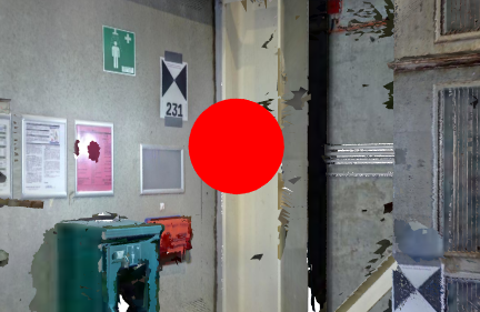
360° Panoramas
|
When you click on one of the spheres, the camera moves to its center, overlaying the model with the panorama image captured at that position. You can only rotate the camera while inside a panorama sphere. Zooming in and out can be done using the mouse wheel (or by pinching/spreading on mobile devices). |
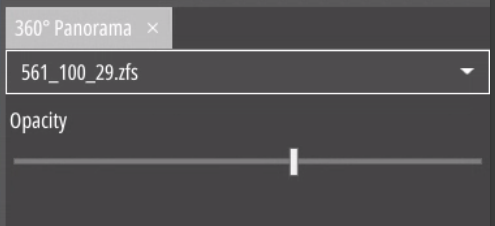
The additional context menu contains the panorama options:
|
You can choose the most recently activated panoramas in chronological order from the drop-down list. Choosing one transitions the view to that specific sphere. |
| “Opacity” slider adjusts the transparency of the overlaid panorama image, allowing you to increase or decrease its visibility. | |
|
To exit panorama mode simply click on the “Toggle display of
360° panorama centres” button
[ |
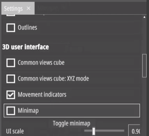
Minimap
|
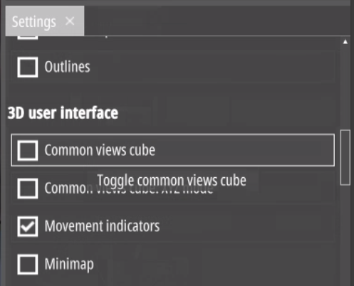
Click on the “Settings” button
[ |
|
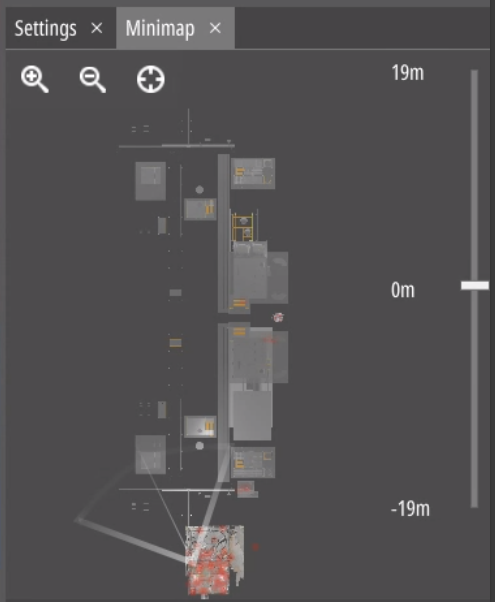
Subsequently, you can move (using the left mouse button) and rotate (using the right mouse button) the camera, directing it precisely to a point on the map with a left or right click. The 90° angle depicted indicates the camera’s field of vision. |
| You can zoom in and out with the magnifying glass icons. | |
| With the bar on the right you can change the camera’s height. The lower half represents the total height of your model. |
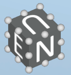
Common Views Cube
|
Click on the “Settings” button
[ |
|
The cube in the upper right corner of the screen gives you directions: N - North, W - West, S - South, E - East, U - Up, D - Down. |
| Clicking on any face of the cube or the small spheres connecting two or three faces will orient the camera to look straight at that face or faces. For instance, clicking on Up will direct the camera to point straight down. | |
| In the “Settings” menu, you have the option to toggle the visibility of the cube, switch between compass and XYZ modes, or make other adjustments. |
To customize text on the cube faces, modify the model’s configuration file. Add the following line to the defaultconfig.upv file:
"CommonViewsCubeText": " S \| E \| N \| W \| U \| D "This will allow you to display the specified text on the faces of the cube.