Drawing
|
|
UPV can automatically create a technical “Drawing” from the 3D model. |
Create Drawing
Select an object.
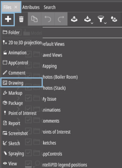
Go to the “Files” tab and select “Drawing” from the “Add” drop-down menu.
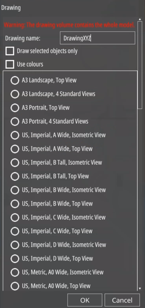
The name you define (e.g., “DrawingXYZ”) for the drawing will be displayed within the drawing if a text field within the drawing border file (.svg) is marked as ###DRAWINGNAME###.
After choosing the name, select the template you want to use. The list shows all templates defined in the drawingtemplates.json file.
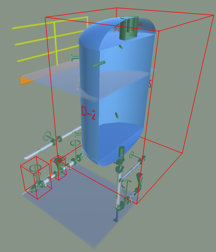
If the volume clipping tool is used then the drawing creation process will consider the clipping and only draws the parts inside the specified volume.
It is possible to create a drawing of the selected 3D objects only by use of the checkbox “Draw selected objects only”.
The checkbox “Use colours” draws the objects in their actual colour used in the 3D model instead of creating them in black and white.
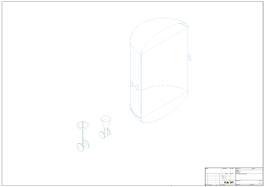
The image below shows an example of an isometric drawing created
in the UPV Demoplant using volume clipping and the
option draw selected objects only.
Viewing the Drawing
|
|
Drawings can be opened by clicking the “Open” button in the “Files” tab next to the drawing. |
Saving the Drawing
(licence for SimpleDrawingModule is needed)
|
|
In order to “Save” any work on drawings, a licence is needed. Drawings can be saved as .svg, .pdf, .acad.pdf and .png files. |
.acad.pdf files are the recommended file type for AutoCAD imports if normal .pdf files do not yield good enough results.