Tutorial 1 - Tank with nozzles
This tutorial explains how to build and bulkload a storage tank symbol for SmartPlant 3D.
Find out which parameter names you need to parameterise the symbol in SmartPlant 3D. Standard names may be found on the CustomInterfaces tab of C:\Program Files\SmartPlant\3D\CatalogData\BulkLoad\Datafiles\Equipment.xls. You will find these names also on the Attributes tab of 3D SymbolDesigner’s Config.xls.

Open 3D SymbolDesigner.
Open a new symbol project (
 in the
File menu).
in the
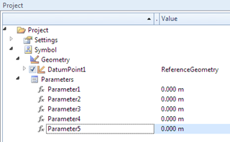
File menu).We need five parameters: parVesselLength, parVesselDiameter, parSupportLength, parSupportHeight, parSupportThickness. First of all you must select the Parameters item in the menu tree. Then press the Parameter button (
 ) five times.
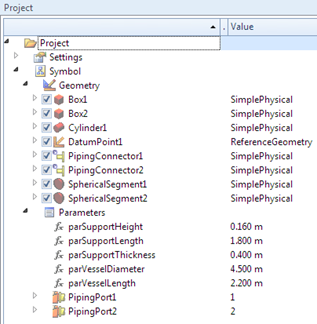
This adds five new parameter items to the project tree:
) five times.
This adds five new parameter items to the project tree:
Rename the parameters: click on Parameter1 in the menu tree (press F2 if necessary), and enter parVesselLength. Repeat this for Parameter2 to Parameter5 with parVesselDiameter etc.:
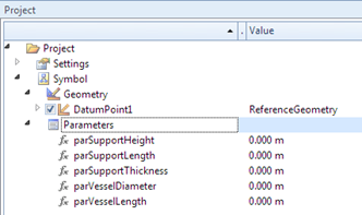
The table of variants should now look like:

Now enter the default values for the parameters into the table:

Rename the “Default” variant and rename the SmartPlant 3D parameter mappings: select the Parameter1 cell and click the right mouse button. In the context menu select the Set SmartPlant 3D attribute. Choose the right attribute in the list box, check the Occurrence attribute and press the Apply button (add OA: in front of the parameter name, if the parameter is an occurrence attribute, i.e. an attribute which may be modified at runtime in SmartPlant 3D). Repeat this for Parameter2 to Parameter5. 3D SymbolDesigner checks the spelling.
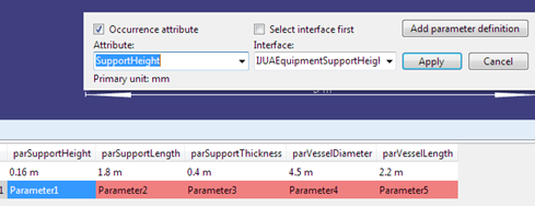
The parameters now are valid and the background colour turned to green:

Select the Project.Symbol.Parameters node and click twice on the Add piping port (bolted preset) toolbar icon (
 ) to add two pipe
ports and twice on the Add piping connector button
(
) to add two pipe
ports and twice on the Add piping connector button
( ) to add two
nozzles.
) to add two
nozzles.Click twice on the Spherical Segment button (
 ), once on the
Cylinder button
(
), once on the
Cylinder button
( ) and twice on
the Box button
(
) and twice on
the Box button
( ) to add the
primitives for the tank geometry. The symbol tree should now look
like:
) to add the
primitives for the tank geometry. The symbol tree should now look
like:
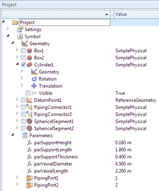
Uncheck (i.e. hide) all primitives except Cylinder1 and expand the Cylinder1 node in the menu tree:
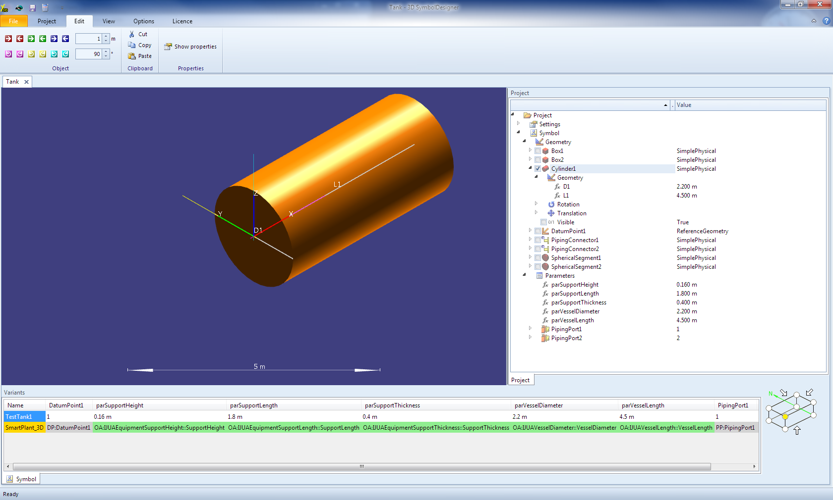
Enter parVesselLength into the formula for the cylinder’s length (L1).
Enter parVesselDiameter into D1.
Zoom out/in (
 /
/
 ) until you see
the full cylinder in the view:
) until you see
the full cylinder in the view:
Check SphericalSegment1 and enter 180 deg or 180° into the formula of Rotation.Z:
The semisphere is now visible on the left side of the cylinder: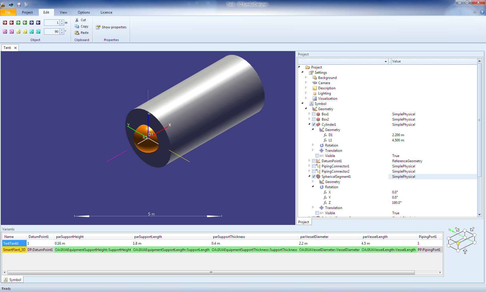
Enter parVesselDiameter into Geometry.D1 and parVesselDiameter / 4 into Geometry.R1:

Switch to wireframe mode (
 ) and tick the
SphericalSegment2 node, enter parVesselDiameter into
Geometry.D1, parVesselDiameter / 4 into Geometry.R1 and
parVesselLength into Translation.X of
SphericalSegment2:
) and tick the
SphericalSegment2 node, enter parVesselDiameter into
Geometry.D1, parVesselDiameter / 4 into Geometry.R1 and
parVesselLength into Translation.X of
SphericalSegment2:

Tick the Box1 and Box2 nodes and enter parSupportThickness into Geometry.L1 and parSupportLength into Geometry.L3 of both boxes. The supports should reach into the tank, so the formula for Geometry.L2 of both boxes is parVesselDiameter / 4 + parSupportHeight.
The formula for Translation.Z of both boxes is - 3 * parVesselDiameter / 8 - parSupportHeight / 2.
Enter parVesselLength into Translation.X of Box2 to translate the box.
Rotate Box2 by entering 180 deg into its Rotation Z.
Tick PipingConnector1 and PipingConnector2. Rotate PipingConnector1 by entering 180 deg into its Rotation Z.
Enter - parVesselDiameter / 2 into Translation.X of PipingConnector1.
Enter parVesselLength + parVesselDiameter / 2 into Translation.X of PipingConnector2.
Set Geometry.L1 of PipingConnector1 and PipingConnector2 to parVesselDiameter / 2.
The modelling of the tank symbol is now finished:
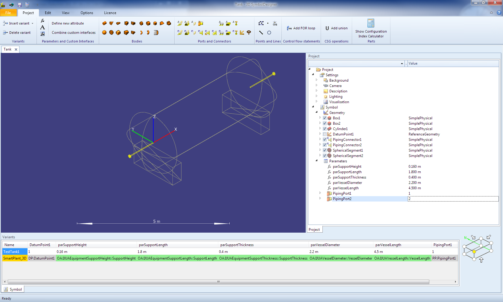
Press the toolbar button (
 ) to export the
symbol to SmartPlant 3D.
) to export the
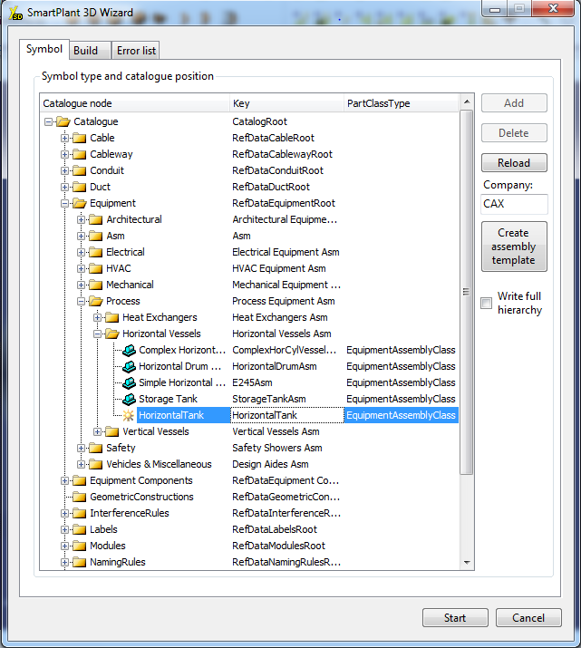
symbol to SmartPlant 3D.Select the parent node of the new symbol in the catalogue tree view on the first tab (if you see only a node named “Catalogue”, double click it to open the tree). Press the Add button:
Select the new node and enter the name in the Catalogue node column and description of the new symbol class in the Key column (e.g. HorizontalTank):
Keep this item selected and click on the Build tab:
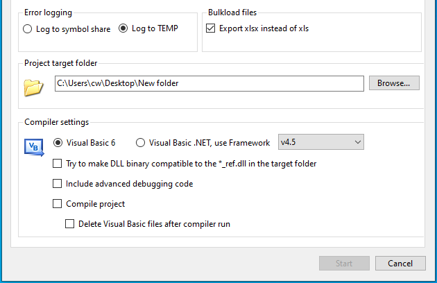
Click Browse… to select a target folder for the Visual Basic Project and the bulkload sheet.
Uncheck all items on the Compiler settings frame.
When Visual Basic 6 is installed on your machine: Tick Compile project.
Click on the Start button. Before the export starts, 3D SymbolDesigner checks if the parameters and the used variant names are valid (see 0 Naming rules). This will avoid afterwards errors during the bulkload process. The occurred errors are shown in the Error list tab. By pressing an item of the list the cursor will move to the corresponding cell in the table.
Optionally: Export of a 3D PDF datasheet (see: Export of a 3D PDF datasheet)
Press OK to close the SmartPlant 3D Wizard window. Now you may close the CAXperts 3D SymbolDesigner program.
 If
Visual Basic or Visual Basic .NET is not available: Please compile the
resulting Visual Basic project on a machine where Visual Basic is
installed and “register” the DLL on the target system.
If
Visual Basic or Visual Basic .NET is not available: Please compile the
resulting Visual Basic project on a machine where Visual Basic is
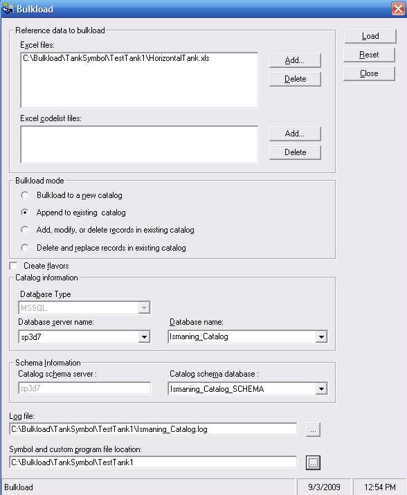
installed and “register” the DLL on the target system.Save and bulkload the Excel file using the append mode of the Bulkload tool provided with SmartPlant 3D:
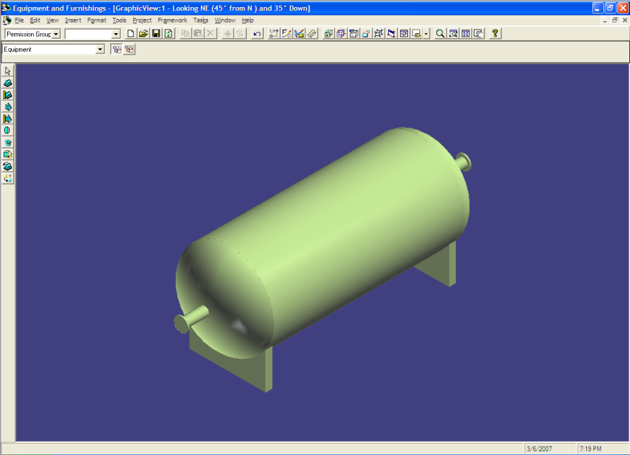
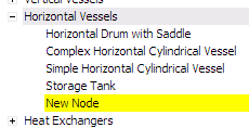
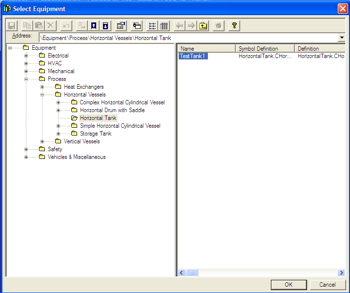
After the bulkload the new symbol is available in the catalogue of SmartPlant 3D:
After placement, the symbol looks like: